


Put a number on the pressure load
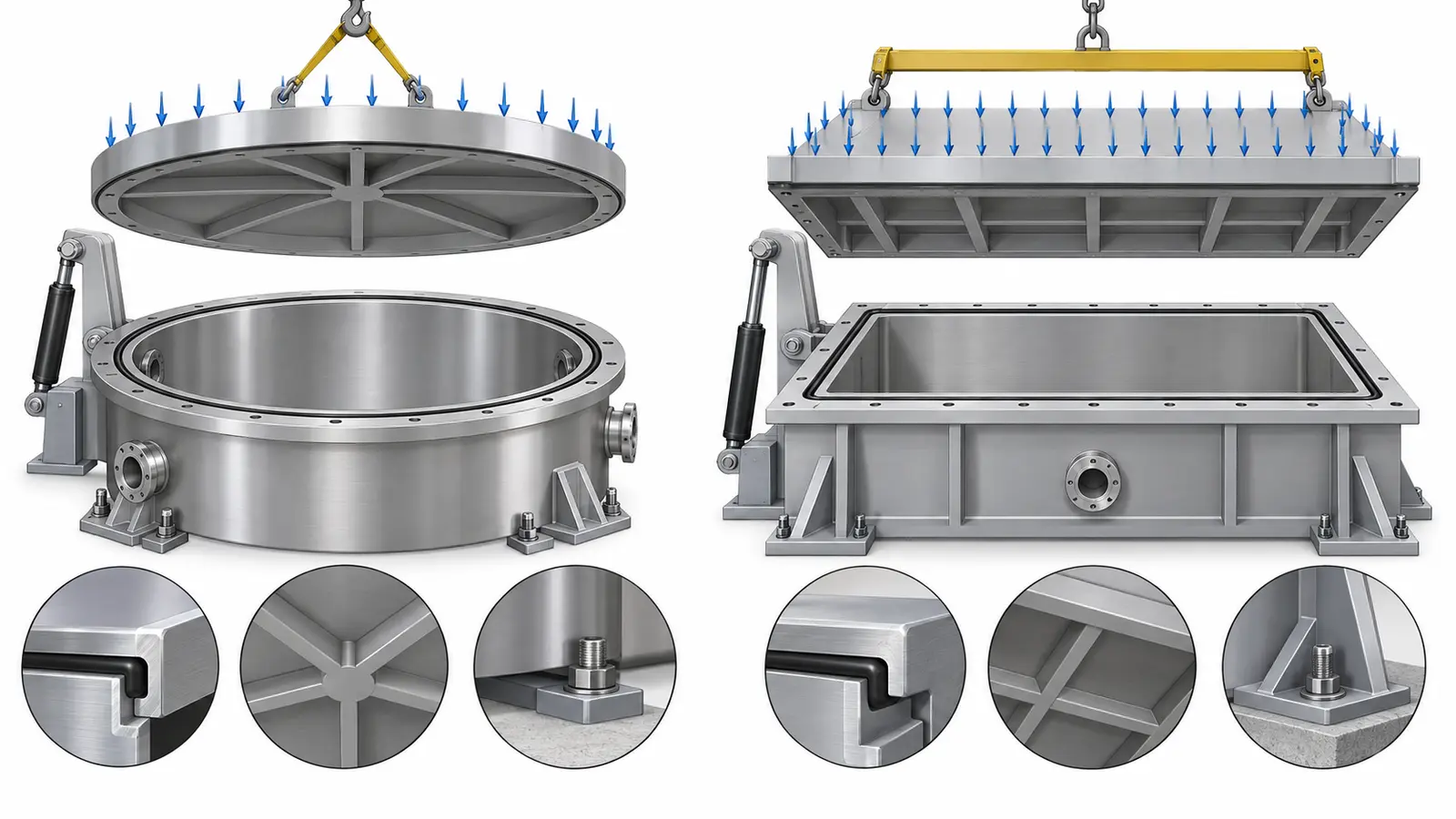
The net pressure force on a flat projected area is F = Δp × A. Use the difference between external and internal absolute pressure, not the pump’s pressure reading alone. This gives a resultant force; it does not calculate stress, bending or a safe thickness.
Illustrative example: take a circular loaded area 300 mm in diameter with approximately 101 kPa pressure difference. Its area is π × 0.15² = 0.0707 m². The resultant inward force is about 7,140 N, or 7.14 kN. The selected dimensions and pressure are illustrative, not a recommended chamber configuration.
For a 300 mm × 400 mm projected rectangle under the same assumed differential, the force is approximately 12.1 kN. A similar-looking cover can therefore carry a materially different load. The actual loaded area must be identified from the seal and support geometry.
As internal pressure becomes small relative to atmospheric pressure, further reduction adds little to this particular external-pressure load. That does not make deeper vacuum easier in every respect: gas load, cleanliness and sealing performance remain separate challenges.
Include other credible load cases in the engineering review, including thermal gradients, attached equipment, handling loads and any possible positive pressure. Vacuum-only hardware must not be pressurized or tested under an unreviewed condition.
Follow that load into the chamber body
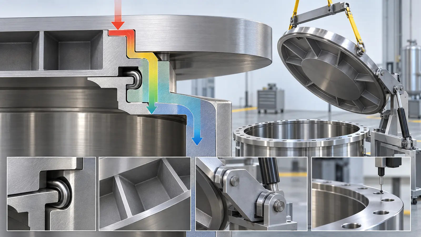
The lid transfers load through its contact and support arrangement into the chamber. The hinge is not automatically the pressure-load support, and a bolt pattern does not by itself establish a fully clamped plate boundary.
Support conditions change the answer
A continuous bearing land, spaced fasteners, a compliant seal and a partially supported edge all influence deformation. A theoretical plate solution with idealized restraint can be a useful screening model, but it must represent the actual joint closely enough to support a decision.
Review the mating flange at the same time as the cover. A thick lid on a flexible chamber rim can still produce uneven seal compression. Narrow ligaments around ports or fastener holes may control the local response even when the central plate looks robust.
Ports and pockets interrupt the load path
A viewport opening, recessed heater pocket or coolant channel removes material from the structural section. The designer must consider its position and remaining wall, not subtract volume from a mass estimate and stop there. Changes near the seal may be more important than similar changes near a well-supported region.
This interface-first approach fits the broader semiconductor equipment parts manufacturing plan: the lid, chamber rim and attached components should be reviewed as an assembly before their drawings are released separately.
Set a seal-movement limit as well as a stress limit
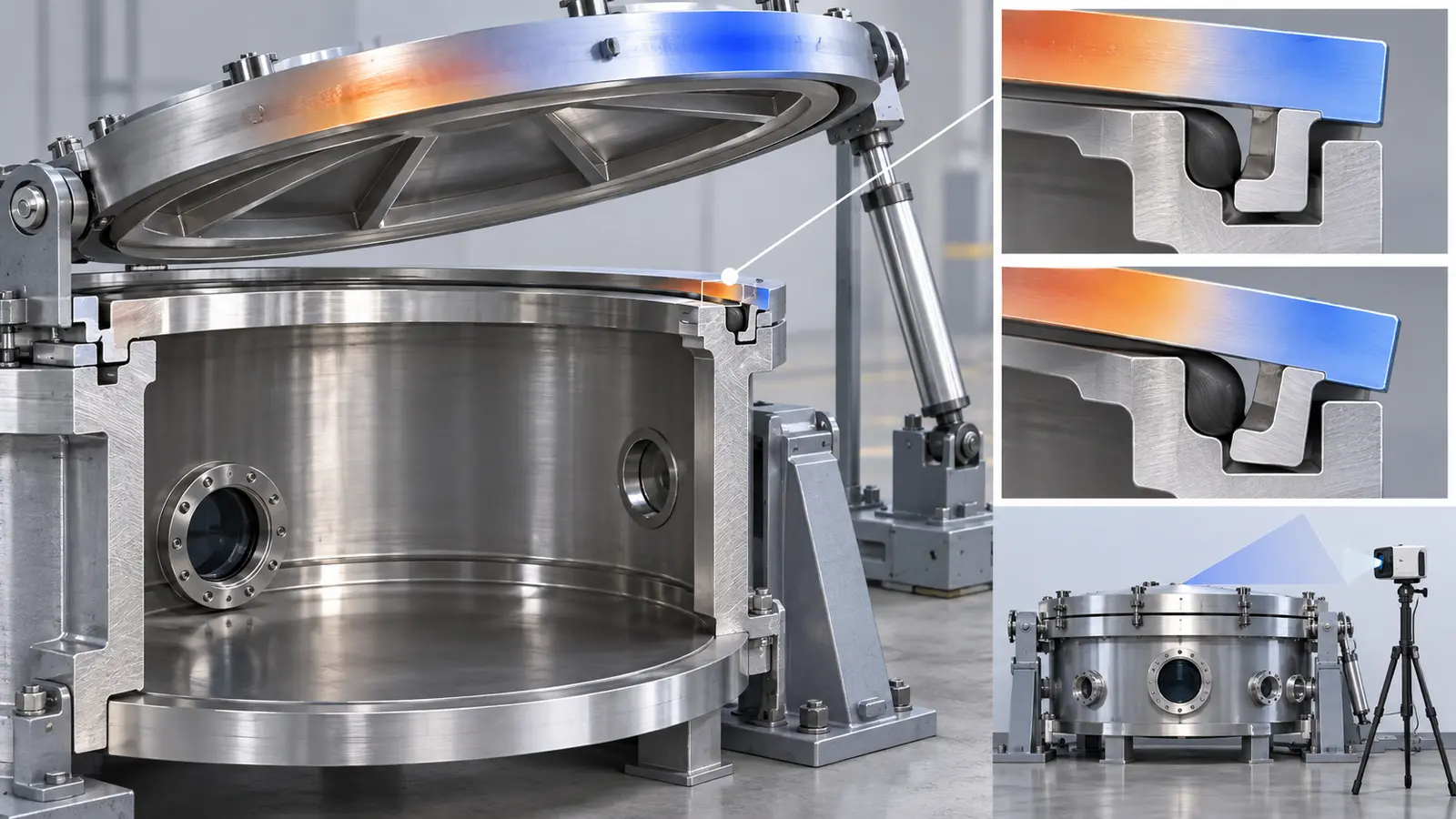
A lid may remain below an allowable material stress yet move enough to affect sealing or wafer alignment. Structural survival and functional stiffness are different acceptance criteria.
| Design check | Functional question | Needed input |
|---|---|---|
| Stress and stability | Can the part withstand the assessed load cases? | Material condition, geometry, restraint and appropriate design criteria |
| Seal-land movement | Does the joint retain acceptable compression around the perimeter? | Seal geometry, assembled gap and allowed movement |
| Port alignment | Will connected parts tolerate displacement and rotation? | Mating tolerances and allowable interface loads |
| Repeated operation | Do opening and pressure cycles change the behavior? | Duty cycle, wear points and verification plan |
For an elastomer face seal, define the hard-contact and compression arrangement. Do not assume the ring should carry every closure load. Equally, do not add a hard stop without checking that its dimensional chain produces the intended seal compression.
A thermal cycle can change that chain. An aluminum lid on a stainless body may expand differently, while an unevenly heated single-material lid can bow. Evaluate the relevant temperature distribution rather than applying one uniform temperature to every component because it is easier to model.
Trade thickness against ribs, span and handling mass
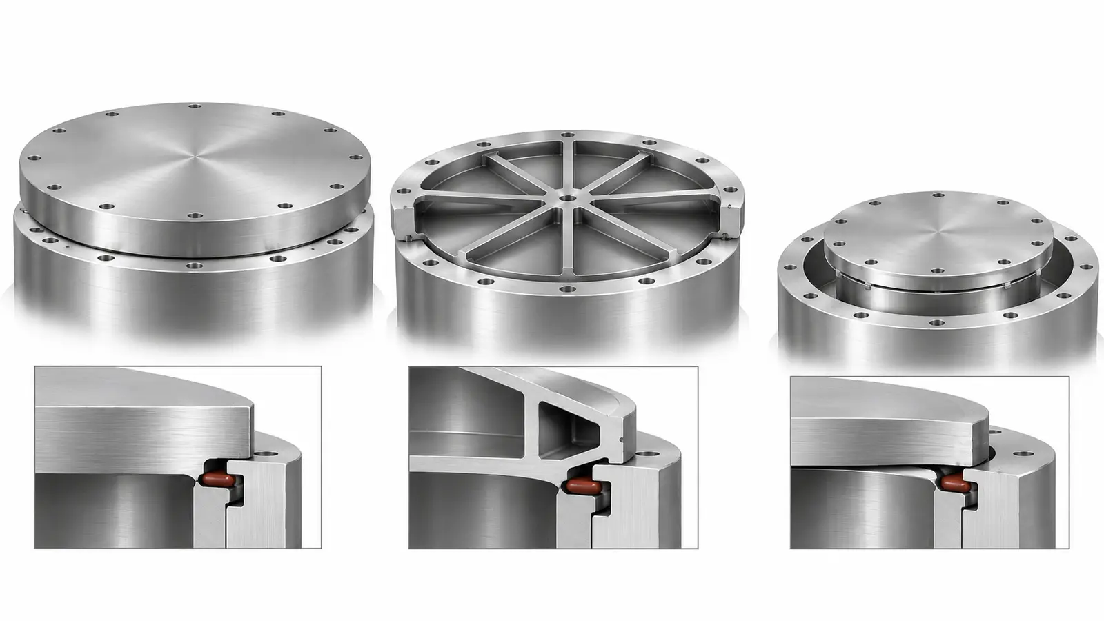
Increasing thickness is one design lever, but not the only one. Reducing unsupported span, changing the support land, relocating an opening or adding suitably designed reinforcement may address the controlling deformation more efficiently.
Each change brings manufacturing consequences. Integral ribs remove more material and complicate access. Welded reinforcement can introduce distortion. A domed or formed cover changes the fabrication route and may conflict with the required opening envelope. The right answer depends on the assembly, not on a preferred shape.
Per machined chamber lids, consider balanced material removal, workholding support and inspection after unclamping. A flatness result taken while the part is forced against a fixture may not describe the released component.
Material choice also changes the trade. Aluminum reduces density and often helps heat distribution but has lower elastic stiffness than common austenitic stainless grades. Stainless can provide a stiffer section of identical geometry at greater mass. Compare designs that satisfy the same functional requirements rather than assuming equal thickness means equivalent performance.
Jucheng Precision can review manufacturability for the lid, seal face, mounting interfaces and related custom mechanical parts. Structural sizing and equipment safety acceptance must remain tied to an appropriately qualified design review, not a machining supplier’s general tolerance statement.
Design the opening operation, not just the closed lid

Once vented, a heavy lid becomes a handling problem. In semiconductor equipment, opening also exposes a clean volume and creates opportunities to damage seals or generate particles.
- Controlled venting: establish the approved condition for opening; do not rely on pulling the lid to determine whether pressure has equalized.
- Supported travel: provide a suitable hinge, lift or handling arrangement for the complete moving mass.
- Positive retention: prevent unintended closing and evaluate pinch and crush hazards throughout travel.
- Service clearance: allow removal of shields, seals and fasteners without scraping process-facing surfaces.
- Protected resting position: keep the sealing face away from benches, dirty contact surfaces and loose tools.
- Utility management: ensure attached hoses, cables and instrumentation do not become lifting restraints.
A counterbalance that feels comfortable at one angle may not control the complete motion. Likewise, a retaining device needs assessment for the actual load and foreseeable failure modes. Use the equipment owner’s machinery safety process to define required interlocks and retention; this article is not a substitute for that assessment.
A full-scale mechanical access prototype can reveal collisions and awkward servicing early. A non-load-rated mock-up should only evaluate layout, never demonstrate safe vacuum operation.
Close the drawing with an inspection and verification plan
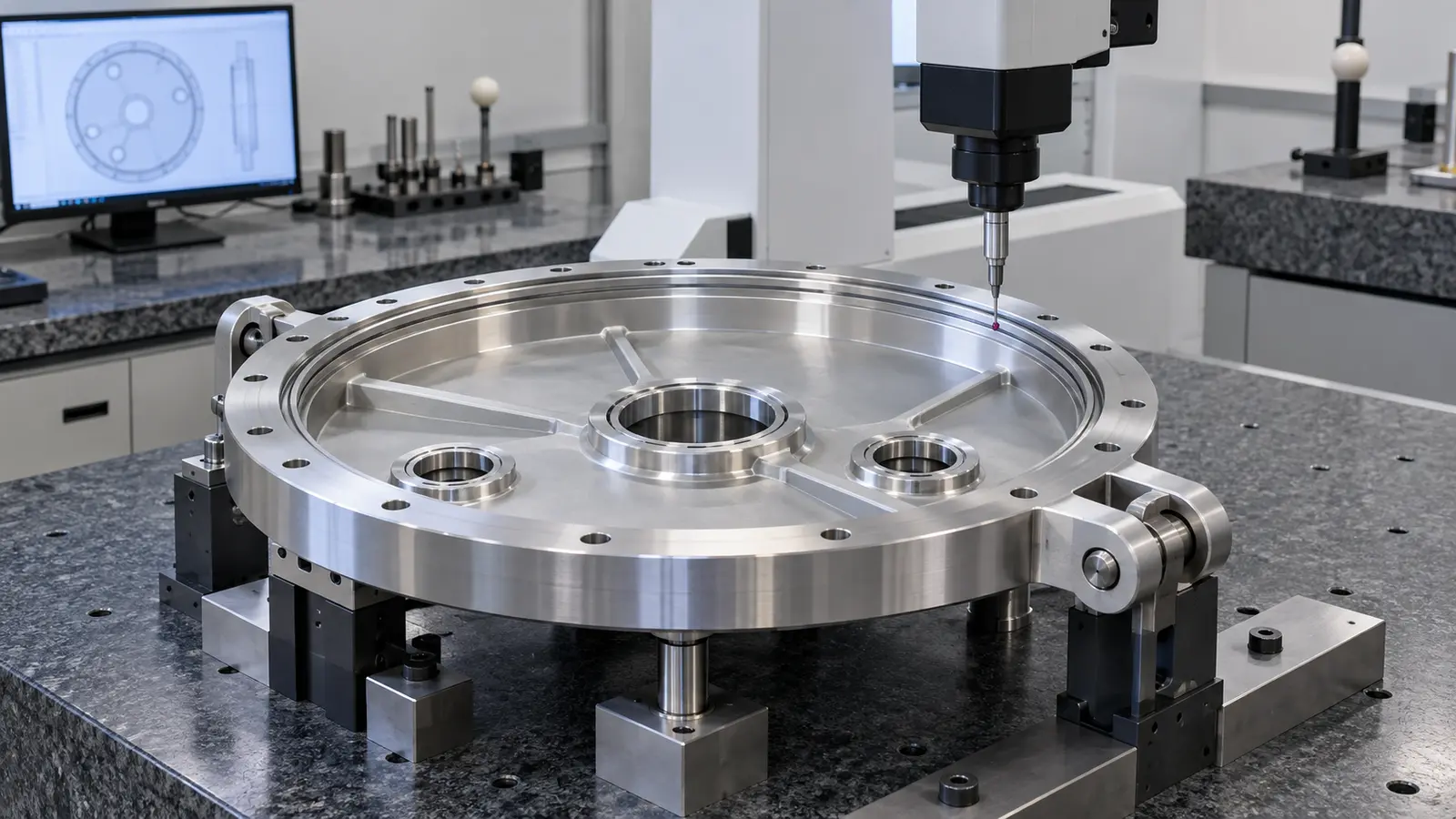
Define which surfaces are measured, in which restraint condition and at what stage after manufacturing. Seal-land flatness, groove geometry, port position and local defects deserve explicit attention. A general all-over tolerance does not explain what determines lid function.
- Review structural and functional calculations for the approved geometry and material condition.
- Confirm critical dimensions on the finished, appropriately supported part.
- Inspect the seal path and treatment boundaries before assembly.
- Verify closure alignment and the approved opening/retention operation.
- Complete agreed leak and thermal checks on the relevant assembly configuration.
- Document any changes to hardware, seals or support conditions before release.
Keep the resulting evidence in the design and procurement package. A lid delivered to a correct drawing may still be unsuitable if the mating rim or installed hardware differs from the analyzed assembly.
How thick should a vacuum chamber lid be?
There is no safe universal value. Required thickness depends on span, shape, openings, material condition, supports, load cases and allowed deformation. Establish these inputs before selecting a plate thickness or reinforcement scheme.
Can atmospheric pressure replace lid clamps?
It should not be treated as a complete closure or safety strategy. The assembly must seal before evacuation and remain controlled during venting, maintenance and abnormal conditions. Retention and closure requirements need a system-level assessment.
When does a viewport need separate review?
Whenever it is part of the pressure boundary. Its material, geometry, mounting and rated conditions must be appropriate to the application. Do not treat an ordinary transparent sheet as an interchangeable vacuum-rated window.

