


The short answer
A water pump housing succeeds when its bearing support, seal bore, mounting face, ports, and fastener pattern hold their relationships after casting, machining, and assembly. The outside shape matters, but a clean-looking casting can still leak or misalign if the machining datums do not connect those interfaces to one another. For a prototype, the most useful manufacturing plan is the one that proves the critical fits early and identifies which features must be machined, measured, and tested together.
That is why water pump housing machining should be planned from the assembly drawing backward. Start with the impeller or shaft axis, the seal arrangement, and the engine mounting interface. Then decide whether the housing should be machined from billet for a functional prototype, cast near net shape and finish-machined, or made with a different route appropriate to the required quantity and material.
Contents
Start with the interfaces, not the outer profile
A water pump housing is an interface-rich component. Depending on the design, it may locate a bearing or shaft, support a seal, bolt to an engine or module, and route coolant through inlet and outlet ports. Each feature has a different consequence if it moves: a mounting-face error can create gasket compression problems, a misplaced bearing bore can affect rotor or impeller clearance, and a poor seal bore can compromise the seal even when the external dimensions look correct.
Mark the functional surfaces on the drawing before selecting a machine operation. Identify the primary axis, the mounting plane, port centers, threaded features, and any surfaces that control a cover or mating component. A useful review asks which features share a datum, which can tolerate independent location, and which need to be measured in the same setup. This avoids treating every dimension as equally important and helps engineering, machining, and inspection teams work from one functional definition.
Wall thickness and casting geometry also affect how those interfaces behave. A thin wall adjacent to a heavy boss may cool differently, while a rib or enclosed passage can make fixturing and tool access harder. If the housing is intended to be cast, the design review should distinguish as-cast surfaces from machined surfaces and specify enough machining stock to clean up the critical faces without removing unnecessary material.
Choose the process route around volume and evidence
For a one-off or early functional prototype, machining from billet can be a direct way to check envelope, assembly access, and the location of selected bores and faces. It does not automatically reproduce a production casting’s porosity, wall variation, or residual stress, so it should answer the questions that a billet prototype can actually answer. If the pump’s performance depends on a cast internal passage or thin casting wall, the prototype route must represent those features closely enough for the intended evaluation.
At higher planned volumes, a near-net-shape casting followed by CNC machining may reduce the amount of stock removed. The decision depends on geometry, alloy, tooling investment, expected demand, and validation schedule. A process comparison should include tooling lead time, machining allowance, inspection access, finishing requirements, and the cost of changing a design after the first sample. Casting does not remove the need for precision machining: bearing bores, seal seats, gasket faces, and bolt interfaces commonly require controlled finishing.
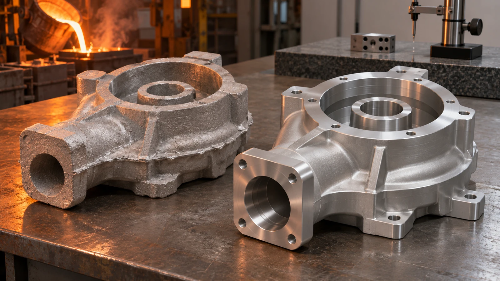
| Route | Useful when | Key limitation to plan for |
|---|---|---|
| CNC from billet | Early fit checks, low quantities, geometry still changing | May not represent casting behavior or production wall structure |
| Casting plus CNC finishing | Repeat production where near-net geometry suits the design | Requires casting review, tooling coordination, and stock control |
| Hybrid or staged route | Prototype learning must transition into a defined production route | Prototype evidence must be labeled by the process that produced it |
For aluminum designs, the project drawing and service conditions should determine the alloy and temper; do not assume every housing uses the same grade. The site’s die casting capability e Servizi di lavorazione CNC are relevant when evaluating a cast-and-machined route. A material page such as aluminum CNC machining can help frame machinability questions, but the final material designation should follow the customer’s approved specification.
Build a datum plan that survives multiple setups
A cast housing rarely arrives as a perfect block. Draft, parting lines, local stock variation, and non-machined surfaces can make a nominally simple first setup unstable. The fixture must locate the casting repeatably without forcing it into a shape that relaxes after unclamping. For thin or uneven sections, excessive clamping force can distort the part and create a measurement pass in-fixture but a fit problem after release.
A practical plan establishes a stable primary datum, rough-machines reference features, and then uses those features to locate the finishing operations. If the bore axis and mounting plane must remain related, finishing them in one setup can reduce the risk of positional error. If a second setup is unavoidable, define how the part is re-seated and how the transfer datum is verified. A probing or inspection step between operations can help catch drift before the last cut, but it does not replace a sound fixture design.
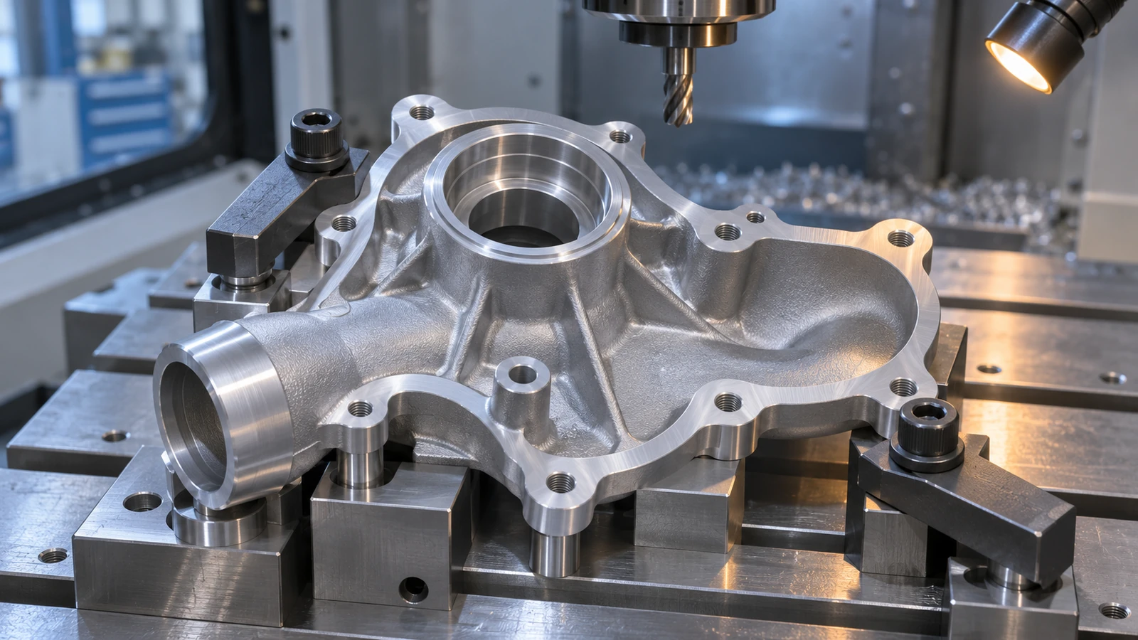
Tool access deserves equal attention. Coolant ports, intersecting holes, and internal cavities may need angled tools or multi-axis access. The design review should identify blind intersections that are difficult to deburr and features that trap chips. Where fluid passes through drilled or milled passages, the drawing should state the cleanliness and burr requirements that matter to the assembly rather than relying on a generic note.
Treat leakage and porosity as separate risks
A housing can leak for more than one reason. A sealing face may be out of flatness, a gasket land may have the wrong finish, a seal bore may be mislocated, or a casting may contain a connected pore path. These causes need different controls. Dimensional inspection can confirm a face or bore; it cannot prove that the casting is free of a through-wall leak path. Conversely, a pressure test does not establish that the mounting pattern or bearing axis is correct.
Define the test method and acceptance criteria with the customer’s drawing or validation plan. Depending on the design, testing may involve pressure decay, a specified fluid test, or another approved method. Record test conditions such as pressure, duration, medium, and fixture arrangement when those details are part of the requirement. Do not infer that a successful test under one condition guarantees every service condition.
If a coating, conversion layer, or other surface treatment is specified, account for its effect on mating dimensions and sealing interfaces. Masking and post-finish measurement may be necessary on selected features. Surface preparation and finishing should follow the material and application specification, not a generic assumption that all aluminum housings are treated in the same way.
Inspect the assembled function, not just dimensions
Inspection should be planned from the risks identified in the drawing review. Critical characteristics may include bore diameter and position, axis relationships, mounting-face flatness, port location, thread condition, and seal-seat geometry. Choose a method that can actually access and resolve each feature. A gauge may be effective for a specific fit, while a coordinate measurement or optical method may be better for positional relationships and profiles.
For early prototypes, agree on which measurements are needed to answer the design question. A complete report for every dimension may be unnecessary for a fit study, while a reduced report that omits the seal interface would miss the main risk. For production, define the inspection plan, sampling frequency, revision control, and traceability requirements before quoting. Keep the test record tied to the part revision and process route so that a later design change does not get compared against mismatched evidence.
Assembly checks can reveal interactions that isolated dimensions do not. A representative mating component or fixture can help evaluate bolt alignment, cover seating, bearing fit, or seal installation. Label any such check as a fit or functional evaluation and state what it does not verify. This makes prototype findings more useful to design and procurement teams.
What to include in a prototype or production RFQ
A useful RFQ package contains the current 2D drawing, 3D model, material and temper, quantity by phase, critical-to-function features, surface treatment, and required records. Mark whether a feature is as-cast or machined, identify datum references, and describe any pressure or leak test. If the design is not frozen, list the changes still under evaluation and clarify whether the requested sample is for visual review, fit, or functional testing.
Ask the supplier to identify assumptions before quoting: proposed process route, machining stock, inspection access, finishing sequence, and risks at thin walls or intersecting passages. A short DFM review can uncover an unmachinable seal recess or a datum that cannot be held through the setup sequence. That discussion is more valuable than asking for a tolerance promise without first confirming what the print controls.
When the project moves from prototype to repeat orders, freeze the accepted revision and process definition. Keep the casting source, machining setup, finishing, and test records connected to that revision. Changes to a port, wall, coating, or seal can alter the inspection plan even if the external envelope stays the same.
FAQ
Can a water pump housing be machined from solid for a prototype?
Yes, when the prototype objective is compatible with a billet route. It can support dimensional fit and selected functional checks, but it may not reproduce the wall structure, porosity, or residual-stress behavior of a production casting.
Which features usually need machining after casting?
The drawing often identifies bearing or seal bores, mounting faces, gasket lands, ports, threads, and locating features as machined. The exact list depends on the assembly and specification; it should not be assumed from the component name alone.
Does a pressure test replace dimensional inspection?
No. A pressure or leak test evaluates a defined containment condition. It does not confirm bore alignment, mounting geometry, thread quality, or every surface characteristic.
What should be agreed before ordering a prototype?
Agree on the part revision, process route, material, quantity, features to inspect, test conditions, and what decision the prototype must support. Also state whether the sample is representative of the intended production process.
A reliable water pump housing begins with a clear relationship between its functional interfaces and a process plan that preserves those relationships. When casting, machining, finishing, and testing are specified as connected steps, the resulting prototype or production part is easier to evaluate and source.