


A steering knuckle is not just a shaped bracket with several holes. It connects suspension, steering, hub, and brake interfaces, so machining decisions have to preserve relationships that determine how those assemblies meet. The difficult part is often not creating one bore or one face; it is holding a network of datums, bearing seats, joint locations, and mounting planes in the relationship defined by the drawing. A useful review of automotive steering knuckle machining starts with those interfaces and the blank condition, then plans how each critical surface will be located and verified.
This is a manufacturing discussion for product engineers and sourcing teams. Vehicle design authority, released drawings, material specifications, and validation requirements remain the source of acceptance criteria.
Contents
- Map the knuckle’s interfaces before selecting operations
- Separate structural form from machined references
- Choose a blank and route that suit the project stage
- Control setup transfer across the bearing and joint features
- Plan inspection as a feature relationship, not a list
- Make the RFQ answerable
Map the knuckle’s interfaces before selecting operations
Begin by identifying what connects to the part: wheel hub or bearing assembly, steering link, suspension joints, brake caliper, and any nearby structural members. The exact configuration varies by vehicle and design. A released drawing may define these connections through bearing bores, tapered or straight joints, bolt patterns, machined pads, and reference datums. Treat each as a functionally related feature rather than an isolated machining target.

A useful first-pass map has three columns: feature, mating component, and drawing control. For example, a bearing seat may be related to an axis and a specified fit; a caliper mounting face may be controlled relative to the hub axis; a joint location may depend on both position and orientation. Do not infer missing tolerances from generic industry practice. Ask the design owner to clarify the requirement when the drawing does not establish the relationship.
This interface map also exposes manufacturing access problems. Deep pockets, angled faces, and features spread across several sides may require multiple orientations. Before toolpaths are programmed, check whether the proposed workholding allows the cutting tool and inspection probe to reach the controlled geometry without creating an unstable clamp or an awkward datum transfer.
Separate structural form from machined references
Knuckles can start from different forms depending on design, material, quantity, and approved supply route. A casting or forging may provide the main structural shape, while machining establishes bearing seats, mounting faces, holes, and other interfaces. A prototype may instead use a machined blank when speed of design iteration matters more than near-net-shape material efficiency. The right choice depends on the product plan, not on a universal claim that one route is always superior.
For a cast or forged blank, the process review should consider stock allowance, draft or forging flow, parting lines, local wall transitions, and how the blank will sit in the fixture. The machining plan needs enough material to clean up controlled surfaces without removing so much stock that stiffness or distortion becomes a concern. If the structural blank is not yet fixed, compare the expected quantity and revision rate before committing to dedicated tooling.
Material and route decisions are connected. Aluminum designs may prioritize low mass, while steel designs may be selected for different load, wear, or durability requirements. The released grade, temper, heat treatment, and property requirements govern. The site’s CNC aluminum material information e alloy-steel machining page can support an initial discussion, but they do not replace design approval or material certification.
Control setup transfer across critical features
The manufacturing plan should translate the drawing datum reference frame into repeatable setup logic. Identify which surface or axis is primary, what secondary features constrain rotation or translation, and how the part is supported while each side is machined. If a feature is finished in one setup and its mating feature in another, state how the relationship is maintained and checked.
Clamping can affect a part before the first cut is made. Irregular cast or forged surfaces may provide inconsistent contact, and thin sections can move under restraint. A setup that forces the blank against a convenient but uncontrolled surface can create a false position that disappears after release. Review support points, clamp direction, and contact area against the actual blank and the drawing’s datum scheme.
One route may rough several surfaces while leaving stock for a later reference-setting pass; another may finish key datums early and use them to locate subsequent operations. Neither is a default recipe. The important practice is to make the sequence explicit and confirm the relevant features after release from the fixture when the drawing or inspection plan requires it. For design iteration or early samples, the site’s prototyping service is a relevant route to discuss before committing to production tooling.
Review the route by operation
| Process question | Why it matters | What to clarify |
|---|---|---|
| How is the blank located? | Blank variation can shift the reference relationship. | Datums, supports, clamp points, and any stock condition. |
| Which features are machined together? | Shared setups can reduce transfer uncertainty. | Feature groups, tool access, and approved sequence. |
| When are critical faces finished? | Later stock removal or restraint may affect them. | Rough/finish sequence and release-state inspection. |
| How is the part protected after machining? | Contact damage or corrosion can affect assembly surfaces. | Handling, packaging, and specified finish requirements. |
Deburring is part of the route, especially around cross-holes, pockets, and edges near mating components. The drawing or agreed workmanship standard should define what is acceptable. Avoid removing material from a functional edge or changing a corner condition simply because it is easier to break every edge uniformly.
Inspect relationships that matter to assembly
A list of individual diameters may not show whether the knuckle’s interfaces align as a system. Inspection planning should connect each characteristic to its datum, acceptance method, and assembly purpose. Depending on the released drawing, that may include bore size and position, face orientation, hole patterns, thread condition, or surface requirements. The method should be capable of accessing the feature and reproducing the specified datum alignment.
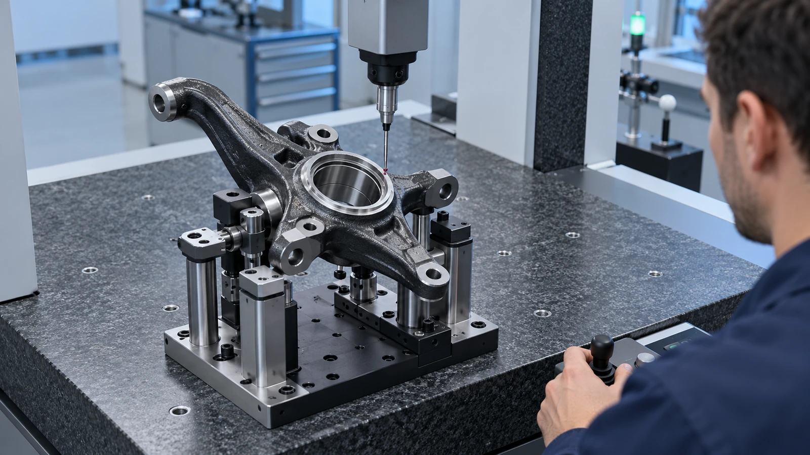
A CMM can be appropriate for defined geometric relationships, while dedicated gauges or other instruments may suit particular sizes or fits. The measurement plan should identify how the part is restrained, which datum features establish alignment, and how measurement uncertainty is handled. Do not publish tolerance claims for the supplier unless the project specification and demonstrated process evidence support them.
If a feature is difficult to measure, raise that during design-for-manufacture review. A probe path, fixture, or inspection model may need to be planned before the part reaches final inspection. For prototype work, agreeing the critical-to-function features before machining helps prevent late disagreement about what data is needed.
Make the RFQ answerable
Send a current 3D model and drawing, material and condition, quantity by phase, critical interface list, required finishes, inspection expectations, and any customer-specific documentation. Include the blank or casting details if those are already selected. If a design is under revision, identify the released version and state which changes are still under review.
A good supplier response should explain the proposed starting form, datum strategy, major setup transitions, inspection approach, and open questions. The goal is not to have a supplier approve vehicle safety or certify a design; it is to expose manufacturing risks early enough for the engineering owner to make an informed decision. Jucheng’s automotive prototyping and manufacturing page provides a relevant business route for discussing part requirements across development stages.
Frequently asked questions
Is a steering knuckle machined entirely from solid stock?
Not necessarily. A project may use a casting, forging, or machined blank depending on design, volume, development stage, and approved supply chain. The drawing and sourcing plan should define the accepted starting material.
Which features should be inspected together?
Features whose position or orientation controls mating assembly should be evaluated in the same datum context where the drawing requires it. The design owner defines the controlling characteristics and acceptance limits.
Why discuss the fixture before finalizing the quote?
Workholding affects tool access, datum transfer, part stability, inspection access, and the sequence of operations. Early review helps identify whether the blank and drawing can be handled as planned.

