


Control-arm machining is easy to misread as a list of holes and machined faces. In assembly, the important relationships usually sit at the bushing bores, ball-joint interface, mounting pads, and the arm’s structural envelope. A hole can meet its diameter while its axis points in the wrong direction; two interfaces can each be in tolerance yet disagree with the vehicle’s locating scheme. The manufacturing discussion should therefore start with how the component is positioned and inspected in the assembly reference frame. The focus here is a drawing-defined control-arm component or development part, not suspension tuning or vehicle performance. Jucheng Precision’s automotive prototyping service supports component development when the required geometry, material, quantity, and inspection scope are clear.
Contents
- Map the pivot and joint interfaces first
- Blank choice changes the machining problem
- Build a setup around the arm’s locating geometry
- Control bore axes and spacing as a pair
- Account for flexible sections and released-part movement
- Keep coatings and bushing fits in the same conversation
- Inspect the arm in its assembly coordinate system
- What to put in a control-arm RFQ
- Frequently asked questions
Map the pivot and joint interfaces first
List each interface that locates or connects the arm: inner pivot bores, bushing seats, ball-joint taper or attachment, fastener holes, and any machined mounting face. Confirm whether the part is a single casting, forging, machined blank, or a fabricated assembly. The process route influences where datums can be established and how much stock is available around the critical features. Use the drawing to distinguish assembly datums from convenient inspection surfaces. If the inner pivots control location, define the relationship between their axes and the outboard joint. If the component is located by a machined face and a hole pattern, make that scheme explicit. Avoid blanket notes such as “machine all holes accurately”; they do not tell a supplier which relationship matters most.
Blank choice changes the machining problem
Control arms can be produced through different routes depending on design, material, load case, production scale, and program stage. An aluminum part may begin as a casting or forging; a steel design may involve a formed or welded construction; a prototype may use a machined billet or a simplified development blank. These routes are not interchangeable. Each has distinct material flow, stock allowance, stiffness, cost, and validation implications.
| Starting form | Potential advantage | Question to resolve |
|---|---|---|
| Machined billet | Direct access for a limited or changing prototype | Does the material-removal route represent the intended design closely enough? |
| Cast blank | Near-net geometry can support complex shapes at suitable scale | Are allowance, blank variation, and datum surfaces defined? |
| Forged blank | Can suit a design whose material form and production route require forging | Is the blank geometry and condition controlled for the machining plan? |
| Formed or welded assembly | May match a sheet-based design and its production concept | How will weld or forming variation affect final machined interfaces? |
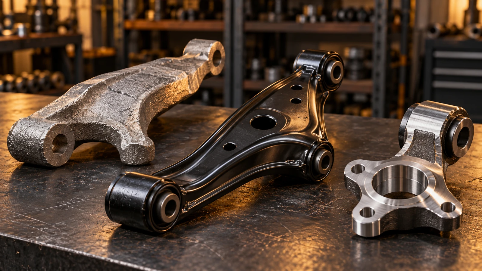
Route selection should follow the project’s required fidelity and quantity, not a general claim that one process is superior. The automotive manufacturing-process guide gives a broad comparison framework; blank-specific DFM depends on the current model and drawing.
Build a setup around the arm’s locating geometry
The arm’s shape may be irregular, with ribs, pockets, bosses, and angled interfaces that complicate fixturing. A fixture must hold the blank securely without forcing flexible sections into a false position. Support near the machining zone can limit vibration, but clamps should not distort a thin section that will later be measured free. If the blank lacks stable datums, an early operation may need to create them before critical holes and faces are finished. Plan the order of operations so that pivot bores, joint features, and mounting faces remain related. Roughing all large pockets at once may release stress or change support. A staged sequence can rough, establish datums, semi-finish, allow the component to stabilize if needed, and then finish the defined interfaces. The actual sequence depends on the blank and specification; these are planning questions rather than guaranteed outcomes.
Control bore axes and spacing as a pair
Bushing bores often need more than a correct diameter. The drawing may control axis orientation, spacing, position, parallelism, or relationship to a ball-joint feature. Clarify whether the bushing is pressed, bonded, sleeved, or installed by another specified method, because the final interface may differ from the bare machined bore. If the bushing is supplied separately, identify whether inspection applies before or after installation. For angled interfaces, a setup that makes one bore easy to machine may make the second difficult to reference. Coordinate measurement can help evaluate multiple features in one frame when access and the drawing support it, while a dedicated fixture may suit repeat checks. The selected method should report the actual characteristic, not just a coordinate chosen for convenience.
Account for flexible sections and released-part movement
Long arms and thin webs can respond to clamping and material removal. A part may appear stable while clamped and move after release. This makes the measurement condition important: define whether the inspection uses a free state, a specified fixture, or another datum setup. Record the support scheme so later measurements can be compared meaningfully. Do not solve every movement issue by tightening tolerances. First review the functional requirement, blank condition, wall thickness, clamping force, tool path, and machining sequence. Where a process step such as heat treatment, welding, or coating occurs, indicate which features are measured before or after it. The automotive materials guide helps frame broad material tradeoffs, but the specified alloy and condition must remain controlled by the drawing or program documentation.
Keep coatings and bushing fits in the same conversation
Corrosion protection, paint, anodizing, or another specified finish may change dimensions or contact behavior at a machined interface. Identify which bores, faces, and threads need masking or post-finish inspection. If the bushing fit is defined on the finished part, state that directly; if the fit is evaluated before coating, clarify how coating is excluded from the seat. Surface appearance and functional condition should be specified separately. A visually smooth arm does not prove bore position, and a dimensional report does not confirm that every edge is free from a harmful burr. Specify edge breaks, contact surfaces, and inspection scope according to the drawing. Avoid adding finish requirements to surfaces where they do not affect function, since every requirement should have an engineering reason.
Inspect the arm in its assembly coordinate system
A useful inspection plan connects inner pivots, outboard joint, and mounting features to one defined frame. Identify the critical-to-fit dimensions and characteristics, then agree on how each will be measured. A CMM, fixture, or combination may be appropriate depending on the arm geometry and required report. Make sure the measuring support does not conceal the very distortion the team wants to understand.
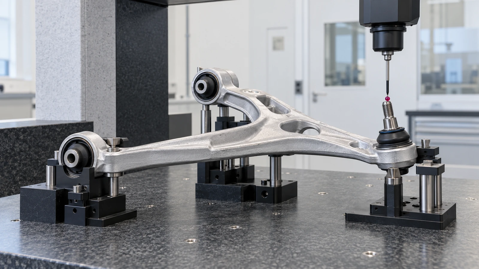
For prototypes, a focused first-article report can answer whether the chosen route produced the assembly interfaces as intended. Include the drawing revision, datum setup, units, measurement condition, and deviations. If a mating bushing or joint is needed to interpret fit, supply its controlled dimensions or an approved interface model. The result should not be presented as a vehicle validation unless a separate vehicle-level test has actually been performed.
What to put in a control-arm RFQ
Provide a controlled model and drawing, material and product form, quantity, blank route if fixed, finish requirements, bushing or joint interface information, datum scheme, and requested inspection records. State whether the request is for a geometry prototype, fit-check part, or production-intent component. Call out critical pivot and joint relationships and ask the supplier to identify fixture, stock, and tool-access assumptions. If the design is not frozen, mark provisional features and the revision expected for the next build. That makes quotation comparisons fairer and reduces the chance that an early component is judged against a requirement that was not yet defined.
Frequently asked questions
Can control-arm holes be inspected independently?
Individual diameters can be measured independently, but assembly fit may depend on the relationship among bore axes, mounting faces, and joint features. Inspection should follow the drawing’s datum scheme.
Is a billet prototype representative of a cast or forged arm?
It can represent selected geometry and interfaces, but the team should document differences in material form and route. It is not automatically equivalent to a production blank.
Should the part be measured while clamped?
Only if the drawing or inspection plan defines that condition. For flexible geometry, measuring the released component may reveal movement hidden by the fixture.