


CubeSat rails do more than define the outside of a small satellite: in a rail-type dispenser, they form the sliding contact interface that constrains rotation and guides deployment. Reliable CubeSat deployer rail manufacturing therefore starts with the selected dispenser’s interface-control documents, not with a generic rail profile. Rail geometry, surface condition, edge treatment, protrusions, coatings, and inspection records must work together as one interface.
A rail can look dimensionally correct on a drawing yet bind during integration if the four contact paths are not aligned, finishing changes the envelope, or a local high spot interrupts the intended contact. The practical goal is not simply to make a straight edge. It is to produce a controlled, inspectable interface that remains compatible with the mission’s specified deployer and fit-check process.
Contents
- Start with the deployer interface
- What the rails actually control
- Dimensions that shape the design
- A manufacturing route that protects alignment
- Material and finish decisions
- Inspection and fit-check planning
- What to send with the drawing
- Common questions
Start with the deployer interface
Before a rail profile is finalized, identify the actual dispenser family, launch integrator, unit configuration, and revision-controlled interface documents. A CubeSat Design Specification provides baseline guidance, but it is not a substitute for the requirements supplied by the launch provider. Cal Poly’s CubeSat Design Specification Rev. 14.1 explicitly states that launch-provider requirements supersede the baseline where they differ. NASA’s Small Spacecraft Systems Virtual Institute also explains that rail-type and tab-type dispensers use different constraint concepts; a structure designed around one should not be assumed to fit the other.
This distinction changes the manufacturing brief. A rail-type design needs the specified contact surfaces and clearance envelope. A tab-based design transfers constraint through tabs and may demand different local features. If the dispenser has already been selected, the drawing package should identify its interface-control document and the controlling revision. If it has not, the design team should treat compatibility as an open systems decision rather than allowing a machine shop to infer it from a nominal CubeSat size.
For a broader look at how prototypes and production routes can support aerospace hardware, see the aerospace prototyping and parts manufacturing overview. The rail article remains narrower: it is about the long sliding interface and the evidence needed to show that interface is controlled.
What the rails actually control
In a rail-based dispenser, four rails extend along the CubeSat’s length. They guide sliding contact and help prevent the spacecraft from rotating inside the dispenser. That function makes rail straightness, parallelism, relative height, and local surface condition more consequential than the rail’s appearance alone. A small mismatch between rails can produce uneven contact: one edge may carry load early while another remains separated, creating friction, tilt, or an unexpected integration force.
Rail surfaces also sit at the boundary between the spacecraft structure and the deployer. Components mounted near the rails must stay inside the approved envelope, and protruding hardware must not enter a keep-out region. A connector, fastener head, or deployable feature can invalidate an otherwise well-made rail if the assembly envelope is not checked in its stowed state. That is why rail manufacturing should be coordinated with the complete outer structure and not treated as a separate machining operation.
These features are often integrated into a frame or chassis. If the rails are machined as part of a larger structure, datum planning becomes central; if they are separate rails, the joint, fasteners, and assembly method become part of the tolerance chain. The chosen architecture should make the rail faces measurable after final assembly, not only while the components are loose on a bench.
Dimensions that shape the design
The CubeSat Design Specification Rev. 14.1 gives useful baseline examples for rail-type designs: it calls for a minimum rail width of 8.5 mm to the first protrusion on each face, limits certain protrusions relative to the rail plane, recommends rail roughness below 1.6 μm, and specifies rounded rail edges. These values belong to that revision and configuration. The mission’s deployer documentation remains controlling, and the design team should confirm how each requirement applies to the actual unit and contact scheme.
| Control item | Why it matters | Manufacturing question |
|---|---|---|
| Rail face location and parallelism | Sets the sliding path through the dispenser | Are all rails referenced from a common datum scheme? |
| Rail width and edge geometry | Defines the contact area and clearance to nearby features | Will deburring and finishing preserve the specified profile? |
| Surface texture and coating | Affects contact behavior and may alter the final envelope | Are requirements stated for the finished surface, not only the raw part? |
| Protrusion and keep-out envelope | Prevents hardware from interfering with the dispenser | Is the stowed assembly checked in its final configuration? |
| Contact length | Determines how much of each rail engages the dispenser | Can inspection verify the intended contact distribution? |
Rather than copying a value into a drawing without context, record its source, revision, units, and inspection method. A nominal dimension alone does not explain whether it applies before or after anodizing, whether it is measured locally or across the full rail length, or how datum alignment is established across a multi-rail structure.
A manufacturing route that protects alignment
One common route is to machine the rail features into a monolithic frame. This reduces part-to-part joints but can make long, slender contact faces sensitive to setup, material removal sequence, and stress release. Another route uses separate rails attached to a frame. It may simplify replacement or allow different materials, but the assembly now depends on joint location, fastener control, and post-assembly alignment. Neither route is universally better; the choice depends on the structure, service concept, interface requirements, and available inspection access.

For an integrated frame, establish datums that relate the rail faces to the body envelope and functional mounting features. Roughing and finishing operations may need separate stages so that the final pass establishes the contact geometry after major material removal. The fixture should support the part without distorting the very surfaces being controlled. If the component is thin-walled or asymmetric, discuss how clamping and release can affect the final free-state geometry.
For separate rails, specify the locating scheme and how the assembled faces will be aligned. A joint can be mechanically secure yet still create a step or twist at the sliding surface. The design should make fastener access, inspection, and any required rework practical. If alignment is established by precision shoulders, pins, or machined seats, those features need clear datum relationships and a defined assembly sequence.
When the project uses subtractive processes, the CNC machining services page can serve as a starting point for discussing the part geometry, quantities, drawing package, and process questions with a supplier. A quote should not be mistaken for verification that the selected dispenser interface has been approved.
Material and finish decisions
Material choice affects stiffness, mass, machinability, joining strategy, and surface treatment. The CubeSat Design Specification recommends aluminum alloy for the structure and names several common alloy families, but the final choice must be checked against mission requirements, structural analysis, thermal design, and the selected dispenser documentation. Do not assume that an alloy designation alone proves suitability for a specific flight application.
Surface treatment is part of the interface definition. Rev. 14.1 specifies hard anodizing for aluminum external surfaces that contact dispenser rails to prevent cold welding. That does not mean every anodize type or thickness is interchangeable. The drawing or process specification should state the required treatment and identify which dimensions are controlled in the finished condition. Masking, coating buildup, edge coverage, and contact-face inspection should be agreed before production.
When the rail is part of an aluminum frame, consider whether the finish changes the contact width or pushes a feature outside the allowable envelope. When a different material or coating is under consideration, obtain approval from the mission’s launch provider or dispenser supplier rather than treating a material substitution as a routine shop choice.
Inspection and fit-check planning
Inspection should answer whether the assembled hardware will follow the intended path through the selected dispenser. A useful plan begins with the datums and critical-to-function characteristics: rail spacing, face parallelism, straightness over the engagement length, relative rail height, edge radius, surface condition, and nearby protrusions. The inspection method should match the feature. A single measurement near one end cannot establish straightness or alignment along a long rail.
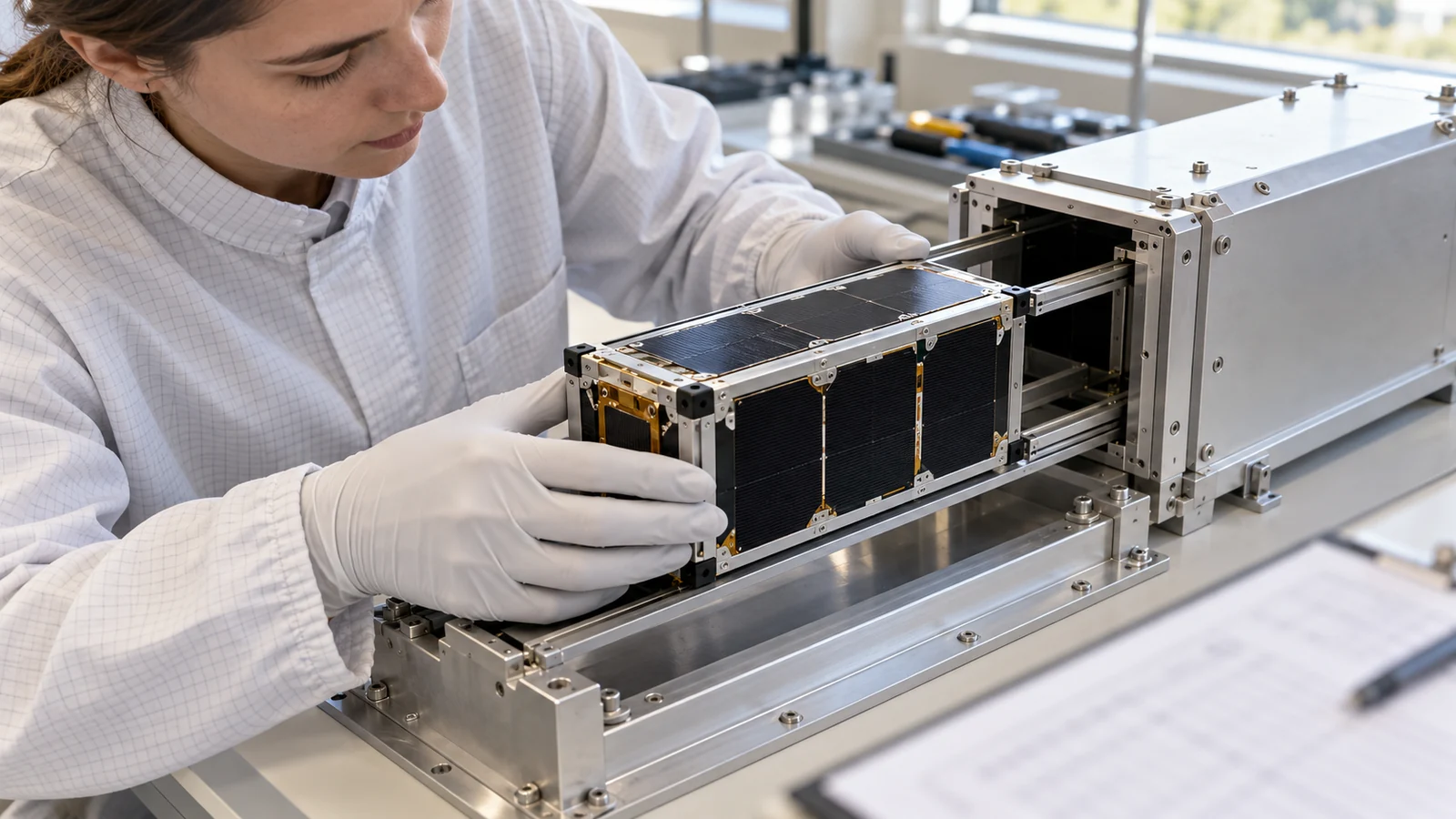
Coordinate measurement, a suitable straightness setup, surface-roughness measurement, and a controlled envelope check may each contribute evidence, depending on the geometry and requirements. The procedure should define how the part is supported, whether it is measured free-state or in a fixture, and whether measurements occur before or after finishing. If the design uses separate rails, inspect the assembled condition as well as the individual components.
A physical fit check with an engineering dispenser or approved gauge can reveal interactions that isolated dimensions miss, but it should not replace documented dimensional inspection. Cal Poly’s baseline specification describes a fit-check process, while the actual launch provider determines the approved mission flow. Record the configuration used, the fit-check result, any approved deviations, and the revision of the interface data.
What to send with the drawing
A clear manufacturing package reduces interpretation risk. Include the controlled 3D model and drawing revision, the selected deployer or interface-control document, critical datums, finished-state dimensions, coating requirements, keep-out boundaries, and any approved deviations. Identify whether rails are integral or separate, what inspection records are required, and whether a fit check will be performed by the customer, integrator, or launch provider.
If the design is still evolving, mark preliminary dimensions as preliminary and avoid presenting them as released acceptance criteria. A supplier can help identify manufacturing risks and propose inspection access, but interface approval belongs to the responsible design authority and launch integrator. That separation keeps manufacturing feedback useful without shifting mission-level decisions to a vendor that may not possess the full system context.
For an early hardware build, a prototyping service discussion can help assess whether the frame and rail features are practical to manufacture and inspect before the design is released. The key is to send the current interface information with the request, not only an image or an unapproved model.
Common questions
Are CubeSat rails universal across all dispensers?
No. Rail-type and tab-type dispensers use different constraint interfaces, and individual dispenser models can have additional requirements. Use the mission’s current launch-provider and dispenser documents to define the released geometry.
Can rail roughness be checked on one small area?
A local roughness reading describes only the sampled area and direction. The inspection plan should identify the specified contact surfaces and sampling method, while separate checks establish rail alignment and straightness over the working length.
Should rails be anodized before or after final machining?
The sequence depends on the design and the finished-state dimensional requirements. If the contact faces are treated, account for coating in the final envelope and define the inspection condition. Confirm the process with the responsible design authority and launch integrator.
Does a successful fit check replace measurement records?
No. A fit check provides system-level evidence for a particular configuration, but dimensional and process records support traceability and help explain the result. Follow the approved mission verification plan.
Sources
- CubeSat Design Specification Rev. 14.1, Cal Poly CubeSat Program
- NASA Small Spacecraft Systems Virtual Institute: Integration, Launch, and Deployment
Note: This article provides general manufacturing-planning information. Mission-specific interface documents and launch-provider requirements control the design and acceptance criteria.

