


An automotive turbocharger shaft is not just a turned bar with an impeller at one end. Its journals, thrust-related surfaces, wheel interfaces, seal regions, and end features must stay in the relationships defined by the assembly design. When those relationships drift, inspection of each diameter in isolation may miss the issue. This guide explains how to review an automotive turbocharger shaft drawing and prototype plan around the rotor axis, datum transfer, and measurement strategy.
The discussion is limited to part geometry and manufacturing communication. It does not specify an alloy, heat treatment, balance grade, turbocharger performance target, or service repair limit. Those requirements vary by design and must be supplied by the responsible engineering authority.
Map every functional surface to the rotor axis
Begin by identifying the surfaces that locate or support the rotating assembly. Depending on the design, these may include bearing journals, a thrust face, a wheel mounting interface, a seal land, and a threaded or retained end. Not every design uses the same arrangement. The drawing should make clear which features establish the axis and which features are controlled relative to it.
Nominal diameters alone do not describe a shaft. A journal can meet its size tolerance while its axis is offset from another journal. Likewise, an end face can meet a flatness requirement while being tilted relative to the rotor axis. A useful drawing review checks the specified runout, coaxiality-related controls, perpendicularity, profile, or other geometric requirements that apply to the actual design. Do not add a tolerance symbol simply because a similar part used it; define the controlled characteristic and datum scheme first.
For an automotive turbocharger shaft, this axis map gives the machinist and inspector a common reference. It also lets the design team distinguish a local size issue from a relationship error that can affect assembly. A section view or feature-control note may help when the shaft has multiple steps, reliefs, and faces whose functional purpose is not obvious from an isometric model.
Separate journal size from runout and surface requirements
Size, form, surface texture, and location answer different questions. A size measurement determines whether a diameter is within its stated limits. Form and orientation checks examine the shape or direction of a feature. Runout evaluates a surface as the part rotates about a specified datum axis. Surface texture requirements address finish characteristics. One measurement should not be treated as a substitute for all the others.

That distinction matters when a drawing has multiple journals or a wheel interface. A micrometer reading can confirm a local diameter at its measurement point, but it cannot by itself show that two journals share the intended axis. A surface-finish instrument cannot establish alignment either. State the acceptance characteristic, datum axis, measurement length or zone where relevant, and reporting method in a way the inspection team can reproduce.
Research on turbocharger shaft repair and rotor dynamics illustrates why shaft condition and alignment are treated carefully in rotating equipment. That research is useful context, not a production tolerance specification for a new automotive design. A prototype supplier should work from the customer’s released geometry and acceptance criteria rather than converting a paper’s experimental values into a drawing requirement.
Plan workholding to protect the reference axis
Long, slender shafts can be sensitive to clamping force, support spacing, cutting loads, and material condition. The manufacturing plan should identify how the workpiece is held while critical diameters and faces are created. If multiple setups are needed, the team should understand how the primary axis is transferred or re-established and how that transfer is verified.
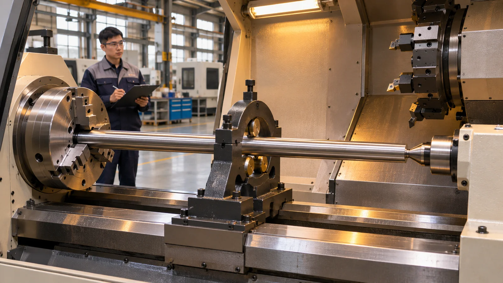
For a prototype, a sequence discussion can start with stock preparation, establishing a reference end or center, machining the major journals and shoulders, and finishing the interfaces that require the final axis relationship. The actual operation order depends on geometry, stock, available process, and tolerances. It should be chosen for the part, not copied from an unrelated shaft. If turning, grinding, or another finishing step is required, identify which operation owns the final size and surface condition.
When a wheel, nut, or other mating component is represented in CAD, use it to review access and assembly interfaces, but do not assume the model is a controlled gauge. Mark critical contact areas and clarify which faces are reference surfaces. A drawing package that includes a 3D model, material callout, revision, and inspection characteristics helps avoid ambiguous handoffs.
Keep material and thermal treatment tied to the specification
Shaft materials and thermal treatments vary with duty, design, supplier chain, and the specified process. Do not infer the grade from a generic turbocharger image or a competitor’s product. The drawing or purchase specification should identify the material standard and grade, condition, any heat treatment, hardness requirement if applicable, and which party provides evidence of conformance.
Thermal processing can change dimensions or surface condition, so the process plan needs to state whether critical dimensions are finished before or after treatment. If a surface is coated, nitrided, ground, or otherwise processed, the drawing should clarify whether the stated dimension applies before or after that step. The part supplier should flag an unclear sequence before machining rather than guess the final condition.
Il mild steel machining overview e aluminum machining overview show examples of the site’s material-navigation content. They are not recommendations for this shaft. The engineering drawing controls material selection; the linked pages should only be used when the specified alloy falls within their described scope.
Design inspection around the characteristic, not the instrument
Begin an inspection plan by listing the characteristics that matter: journal diameters, distances between shoulders, end-face relationships, runout or profile controls, and any specified surface requirement. Then select a measurement approach capable of evaluating each characteristic against its datum reference. A V-block and indicator may be suitable for some checks, but not automatically for every datum scheme or tolerance. A coordinate measuring machine, roundness instrument, or dedicated fixture may be relevant in other cases; the drawing and capability of the method govern.
Agree on how the shaft will be supported during measurement and whether the specified axis is simulated from centers, journals, or a defined datum feature. Record the setup, part orientation, instrument method, and drawing revision when the report is important to design review. This makes two measurement rounds comparable and reduces the risk of treating a setup difference as a part change.
For a hypothetical prototype review, suppose two journal diameters pass size checks but the assembly still shows a positional concern. The next step is not automatically to tighten both diameter tolerances. First review the datum axis, runout requirement, shoulder location, mating component, and measurement setup. This diagnostic sequence points the team toward the relationship that should be evaluated instead of indiscriminately changing the dimensions.
What to send for a manufacturability review
Send the current drawing, 3D model, material specification, quantity, finish and heat-treatment notes, and any required inspection report. Identify the critical-to-function features and the assembly references used by the design team. If the drawing is preliminary, list open decisions clearly. That enables feedback on access, datum strategy, workholding, and inspection without implying that a prototype review validates turbocharger output or durability.
Where CNC turning or milling is part of the plan, the verified CNC machining capabilities page describes the relevant service scope. A specific automotive turbocharger shaft still requires a drawing-based review of material, dimensions, finish, and any secondary processes. No production qualification or performance claim is implied by this article.
Common review mistakes
- Checking journal diameters but overlooking the axis relationship between journals.
- Calling out runout without defining the datum axis or inspection setup.
- Confusing surface finish with roundness, size, or alignment.
- Leaving the before/after heat-treatment dimension condition unclear.
- Using a research paper’s test conditions as an automotive production specification.
- Changing a tolerance before confirming the mating interface and datum scheme.
Frequently asked questions
Does a correct journal diameter prove the shaft is aligned?
No. A diameter check is local. Alignment and runout requirements evaluate relationships to a datum axis or another defined reference and need an appropriate measurement setup.
Should the shaft be balanced during a machining prototype review?
Only if the design or project specification requires that activity and defines the applicable assembly state, balance procedure, and acceptance criteria. This article does not prescribe a balance grade.
Can material be selected from the service or material overview pages?
No. Those pages provide general navigation. The released design or customer specification must identify the exact alloy and condition.
What makes runout data useful?
The datum axis, supporting method, measurement location, instrument approach, and drawing revision should be clear. Without that context, two readings may not be comparable.
Sources and scope
For background on rotating-shaft considerations, see the published turbocharger shaft repair study and the cited rotor-dynamics literature. These sources provide research context only. They do not define dimensions, materials, balance limits, or acceptance criteria for a different automotive turbocharger shaft.

