


A brake backing plate is easy to overlook because it is hidden behind the friction material and caliper. Yet its stamped shape, local stiffness, edge condition, and interfaces can influence how a brake-pad assembly fits together. For a custom or development component, the manufacturing question is not simply whether a blank can be cut: the drawing must distinguish the pad support region from tabs, abutments, holes, and formed features that locate the plate in the surrounding assembly. The term automotive brake backing plate manufacturing describes this drawing-led part and process scope; it does not replace the program’s approved design requirements.
This guide focuses on manufacturing and inspection decisions for drawing-based backing plates. It does not define a vehicle brake design, friction formulation, or performance limit. Those requirements remain with the design authority. The aim is to help engineering and sourcing teams communicate the geometry, material, forming route, and evidence needed for a useful prototype or production quotation.
Contents
- Start with the pad-support and locating interfaces
- Define flatness where the assembly needs it
- Select blank and forming route by geometry and volume
- Control edges, piercings, and formed transitions
- Treat coatings and bonded layers as process interfaces
- Build an inspection plan around the assembly datums
- A practical RFQ package for backing plates
- Frequently asked questions
Start with the pad-support and locating interfaces
Read the drawing by separating the major functional regions: the pad-support area, perimeter outline, caliper or bracket locating features, retention details, and any holes or slots used by the assembly. Identify which surfaces touch another component and which features control installation. A plate that appears symmetric in a flat view may have formed offsets or local features that establish orientation. Include a controlled 3D model when the drawing does not fully communicate those relationships, and name the revision that governs the quote.
For development work, request the mating envelope or assembly drawing when available. It can reveal whether a tab is a clearance feature, a load-bearing stop, or simply a retention point. The supplier should not infer the function from appearance. A useful design review labels critical contacts and states whether the component is measured in its free state, after forming, or while held in a defined fixture. That information prevents disagreements later about whether a measured contour represents the intended installed condition.
Define flatness where the assembly needs it
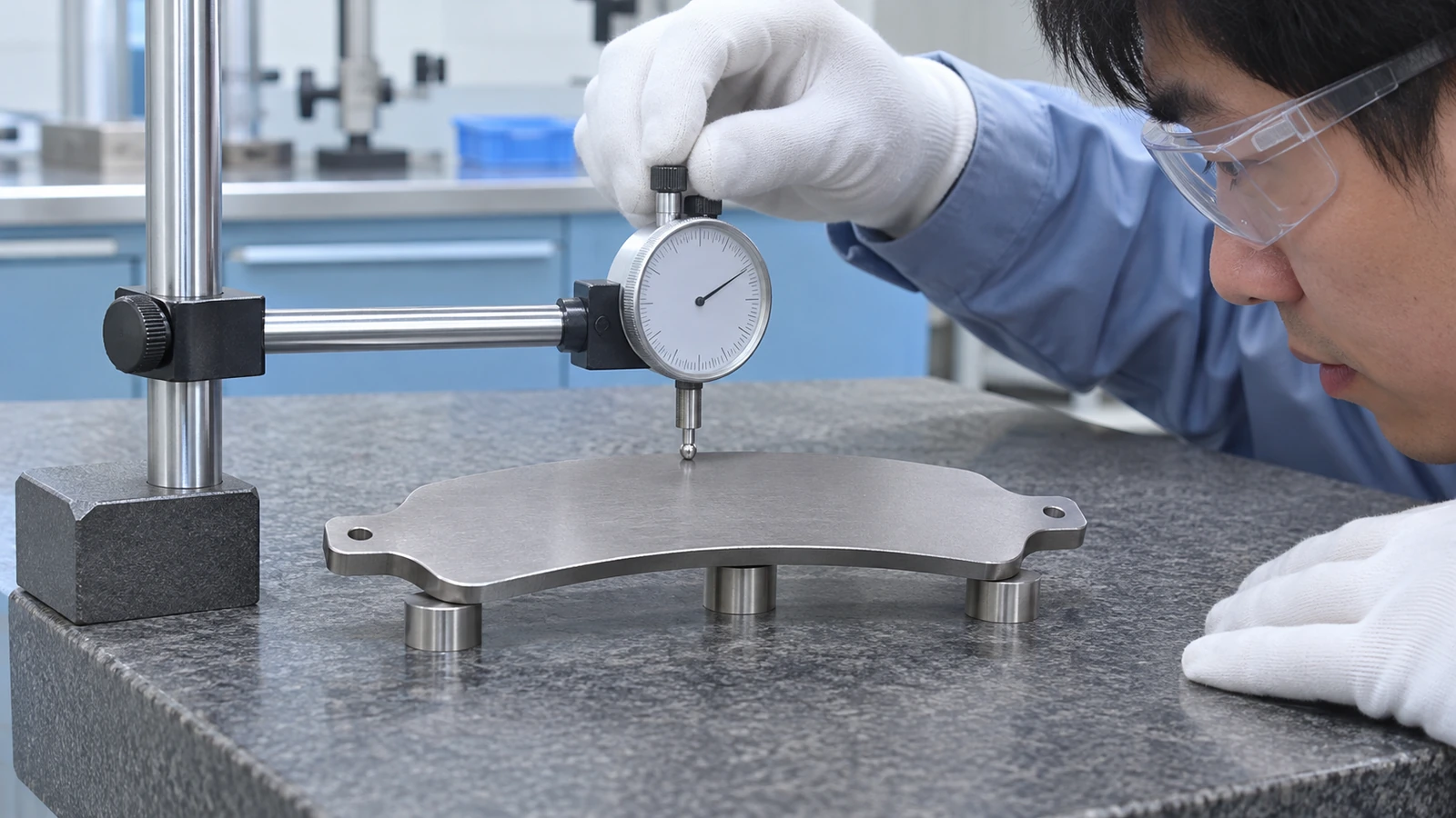
Flatness is meaningful only when the controlled region and measurement condition are clear. The pad-support face may need a different control from a flange or formed ear. If a single flatness callout covers a large profile that includes bends, it may create ambiguity about how the part is fixtured and which area actually matters. Define datums that correspond to assembly location, then apply geometric controls to the surfaces and features that require them. In automotive brake backing plate manufacturing, the controlled flatness region should be tied to the pad-support or assembly interface shown on the drawing.
Stamping and forming can produce springback, local waviness, or a twist that changes when the part is released. Material thickness, blank orientation, tooling condition, and sequence can influence the result. A measurement made by pressing the plate flat against a surface plate may hide its free-state shape. If the acceptance decision depends on restraint, specify the fixture points and clamping method. For prototype lots, compare the measured state with the expected assembly support before changing the tool or introducing a secondary flattening operation.
Select blank and forming route by geometry and volume
Laser-cut or machined blanks can be useful for early fit checks, outline studies, and limited development quantities. They may not reproduce production stamping characteristics such as sheared edges, forming strain, tool marks, or springback. A progressive or dedicated forming tool becomes relevant when feature repetition, output volume, and the required shape justify the tooling investment. The selection should follow the learning question and release plan rather than assuming one process is suitable at every stage.
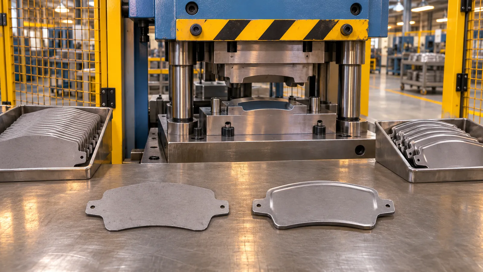
When comparing routes, account for material thickness and grade, bend radii, pierced-feature spacing, tooling access, and any post-form operations. A part cut from sheet may require deburring and edge conditioning; a formed part may need a dedicated check fixture to verify profile and locating features. If subsequent bonding or coating is expected, include those operations in the route comparison because handling and heat exposure can change the part or its surface. The site’s sheet metal fabrication capability is a starting point for discussing custom sheet components; the drawing and program requirements determine the actual route.
Control edges, piercings, and formed transitions
Sheared edges, slots, pierced holes, and notches deserve explicit review. The drawing should state where burr direction matters, where edge breaks are required, and where a sharp edge is prohibited. A uniform instruction such as “deburr all edges” may be insufficient if one edge is part of a locating interface and another is hidden or bonded. Define the acceptance zone around retention features and holes so edge conditioning does not erase a critical shape or change engagement.
Formed transitions should be assessed with the material thickness and intended fit in mind. A radius that is too small for the specified material or process may create cracking risk; a radius that is enlarged without approval may shift a mating edge. The supplier can flag manufacturability concerns and suggest review points, but the designer controls approved geometry. In a prototype, document any deviation or temporary process choice so the sample is not mistaken for a validated production definition.
Treat coatings and bonded layers as process interfaces
Surface treatments, friction shims, adhesive layers, or damping materials may be part of the broader assembly. Their exact specification should come from the customer drawing or approved process documents. Identify areas that must remain free of coating or adhesive, as well as surfaces that need preparation before bonding. Masking boundaries and edge coverage can affect fit, corrosion protection, and later assembly, so they belong in the process review rather than as an informal finishing note.
Any thermal or chemical process after forming should be considered for its possible effect on dimensions and surface condition. That does not mean every backing plate needs an extra finishing step; it means the sequence should reflect the specified construction. Where finish is subcontracted, state the required documents and traceability in the purchase package. The supplier should not claim that a general coating name proves a particular brake performance or regulatory outcome. The performance requirements and verification belong to the responsible vehicle program.
Build an inspection plan around the assembly datums
Inspection should include the outline and thickness where specified, but it should also relate the locating features to the pad-support region. A flat pattern check may confirm hole spacing and perimeter dimensions without revealing post-form twist. A formed-profile fixture may be better for installed shape, provided its locators and restraint are documented. Choose the method for the characteristic under review, not for convenience alone.
For initial parts, agree on a first-article report that identifies the drawing revision, material description, inspection method, and each characteristic included. If a dimension is difficult to measure after coating or bonding, decide whether to inspect it earlier in the route or define an alternate evidence method. Keep raw measurements and acceptance criteria connected. A report should not imply that the part passed a performance test if it only contains dimensional results. Clear evidence boundaries make engineering changes and supplier comparisons more reliable.
A practical RFQ package for backing plates
Send the controlled drawing, 3D model, material and thickness, annual and release quantities, expected prototype stage, forming details, secondary finishing requirements, and inspection expectations. Identify the pad-support zone, locating interfaces, critical bend or pierced features, and any surfaces requiring masking or bonding. Include the mating assembly information needed to understand fit without asking a supplier to infer design intent from a photograph. A complete automotive brake backing plate manufacturing package should distinguish the pad-support zone from formed locating features and secondary-finish areas.
Ask suppliers to call out assumptions about tooling ownership, sample quantities, dimensional reporting, and any secondary operation that could change shape. If the drawing is still under review, distinguish released requirements from open questions. A quote based on that separation is easier to compare and easier to revise when the design changes. Custom fabbricazione della lamiera can support prototype and low-volume discussions, while production stamping choices depend on the final part definition and volume plan.
For broader vehicle component context, see the automotive manufacturing processes overview; the part drawing still controls the material, geometry, and acceptance criteria discussed here.
Frequently asked questions
Does a laser-cut prototype represent a stamped production plate?
It can check outline and selected assembly relationships, but it will not reproduce every forming, shearing, and springback effect. Define which questions the prototype answers.
Should flatness be measured with the plate clamped?
Use the condition stated by the drawing or agreed inspection plan. If restraint is required, define contact points and clamping force or method so results can be repeated.
Can the supplier choose a coating for corrosion protection?
No substitute should be assumed. The specified finish, masking requirements, and acceptance records need approval from the design authority.

