


Una automotive alternator rotor is more than a shaft with a coil: in a claw-pole design, two shaped pole pieces surround the field winding and interleave to create alternating magnetic poles. The rotor’s pole geometry, shaft axis, and assembled mass distribution all affect how the rotating group fits and behaves. For a component drawing, the practical task is to define which features locate the rotor, which establish its phase and air gap, and which need inspection after assembly.
Claw-pole alternator studies link pole geometry and mass centricity with electromagnetic behavior, vibration, and balancing effort. That does not mean a machining supplier can infer electrical performance from a part model. It means the design and manufacturing teams should preserve the interfaces that the alternator designer has established, then report measurements against the drawing and agreed inspection plan.
Why claw-pole geometry is a coupled problem
The claw poles shape the magnetic field across the air gap. Their fingers interleave around the field coil, and the overall rotor rotates inside the stator. Pole profile, axial position, concentricity, and the rotor axis therefore belong to a system rather than a list of unrelated dimensions. Research on claw-pole alternators has examined the influence of pole shape on magnetic noise, while separate work has addressed unbalance control and the mass centricity of claw poles. These studies support careful geometry control; they do not establish one universal tolerance for every alternator.
A drawing review should first identify the surfaces that set the rotor axis, usually bearing journals or shaft seats, and then show how the pole features relate to that axis. It should also distinguish the pole-to-pole assembly relationship from the stator air-gap requirement. A component vendor may measure a rotor feature, but the final air gap depends on the rotor, stator, bearings, housing, and assembled stack.
The buyer should provide the assembly datum scheme, rotor orientation, and any balancing or runout requirement. If the rotor is supplied as a set of subcomponents, clarify which alignment features are controlled at the part level and which are verified after joining. A visually symmetric claw shape is not enough to determine its angular or axial acceptance criteria.
Set a stable reference from the shaft outward
The shaft or bearing journal establishes the rotational reference. The pole pieces, field coil seat, retaining features, and any fan or drive interfaces need to be related to this reference in a way that reflects assembly. If the pole pieces are formed or forged, critical faces may be finish-machined only where the design requires them. If the drawing includes a pilot, register, or shoulder, specify whether it is a locating interface or merely a clearance feature.
For a rotor built from separate components, the drawing package should state how pole halves are clocked and retained. A key, notch, pin, fixture feature, or controlled assembly sequence can provide phase. If the design relies on a pressed or shrink-fitted joint, the interference and material condition must come from the engineering specification. A shop should not select a press fit by copying a generic alternator dimension.
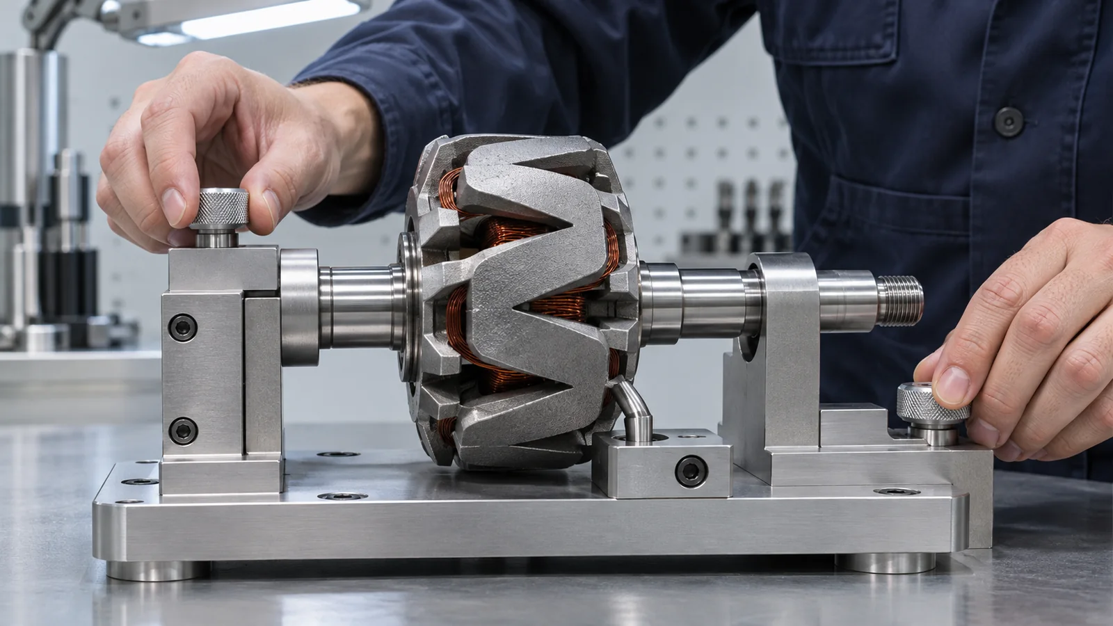
Inspection planning benefits from the same datum clarity. A runout check over a shaft journal can be meaningful only if the setup represents the intended axis. A pole-tip measurement should identify whether it is referenced to the rotor axis, a datum plane, or a temporary fixture. This is why the measurement method belongs in the drawing review, not as an afterthought once parts are on the bench.
Separate forming, machining, and balancing decisions
Claw pole features may be produced by forming or other near-net methods, while shaft seats and selected reference surfaces may require finish machining. The route depends on alloy, geometry, volume, tool design, and the part supplier’s validated process. CNC machining can create or refine accessible features on a prototype, but it is not automatically the best way to produce thin, repeated pole fingers at production scale. A route comparison should consider material flow, distortion, machining access, joining, and the cost of inspection fixtures.
When a prototype uses machined pole geometry, plan workholding so the shaft axis and angular orientation are retained between setups. Clamping on delicate claw features can distort the part; clamping on an unfinished shaft may also create a false reference. The process plan should identify a robust datum surface or temporary fixture that does not damage functional geometry.
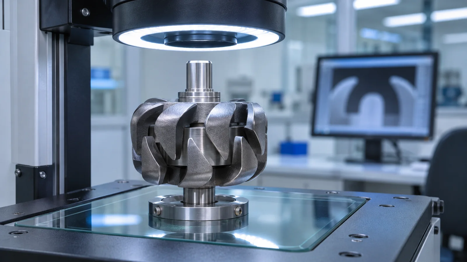
Dimensional conformance and dynamic balance answer different questions. A rotor can meet its nominal dimensions yet still have residual mass eccentricity. Conversely, balancing cannot correct a pole profile or air-gap interface that is out of specification. If balancing is required, define the speed, fixture, correction method, residual limit, and report. If the requirement applies to the rotor-and-fan assembly, do not treat a component-only check as equivalent.
Which features deserve explicit inspection?
- Shaft journal diameters and their relationship to the common rotational axis.
- Axial location of pole faces and the rotor stack relative to shoulders or retainers.
- Radial runout or pole-tip envelope when the drawing assigns a requirement.
- Angular clocking between pole pieces, shaft features, and drive interfaces.
- Joining or retention features, including any specified interference or weld condition.
- Balance evidence at the part or assembly level, as explicitly stated by the specification.
Use a measurement method that corresponds to the characteristic. A caliper may check an accessible overall dimension, but it cannot establish a pole-tip envelope relative to the shaft axis. A CMM, rotary fixture, indicator sweep, or dedicated gauge may be considered according to the drawing and tolerance. Record setup and datum realization for characteristics that are sensitive to fixturing.
For related rotating-part interfaces, the existing guide to electric motor end shield bearing-seat alignment explains why a bearing seat and housing register must be considered together. The component is different, but the datum-transfer question is relevant to alternator rotor assemblies as well.
Material and thermal details must come from the design
Claw poles and shafts can use different materials or conditions depending on electromagnetic, mechanical, corrosion, and manufacturing requirements. The component drawing or material specification must identify grade, heat treatment, coating, and traceability where required. Do not assume that two rotors with similar shapes use the same alloy. The material choice can influence forming behavior, machining response, magnetic properties, joint design, and balance correction.
Thermal processing or joining may shift dimensions. If a rotor is heat treated, welded, brazed, or otherwise assembled after finish machining, the sequence should identify which features are measured before and after that step. Where a coating affects fit, define whether dimensions are inspected before coating, after coating, or both. A report should use the part revision and process state that correspond to the acceptance requirement.
For low-volume prototypes, an automotive alternator rotor may be reviewed through a CNC machining route when the drawing’s accessible features suit a subtractive process. This does not establish alternator electrical output, noise, durability, or regulatory acceptance. Those outcomes require the complete design and validation program.
Questions to resolve before a prototype build
Does pole geometry determine output by itself?
No. It is one contributor within the magnetic circuit and assembled machine. Coil, stator, air gap, speed, control, and thermal conditions also matter.
Can a supplier balance the rotor without assembly information?
Only if the specification defines a component-level balancing setup and limit. Assembly-level balance may include the fan, pulley, or other rotating parts and is not interchangeable with a rotor-only result.
What information helps avoid a misclocked rotor?
A clear angular datum, assembly orientation, mating feature, and inspection method. If the pole pieces are separate, the retention and clocking method should be explicit.
Conclusione
A reliable automotive alternator rotor plan begins at the shaft axis and connects pole geometry, assembly clocking, runout, and balance to that reference. Separating part dimensions from system-level electrical and vibration validation keeps supplier evidence useful without overstating what a component inspection proves.
References
- A Contribution to the Unbalance Control of Claw Poles for Automotive Alternators, Journal of Mechanical Engineering.
- Ansys Maxwell: Analysis Approach for Claw-Pole Alternators.

