


Timing chain guide manufacturing is often discussed as a plastic-part problem, but a guide only works when its contact path, mounting geometry, material behavior, and surrounding chain system are considered together. The guide must support the chain where the design requires it, avoid unwanted interference through its travel, and retain its specified shape under the service conditions defined by the vehicle program. Those requirements turn a seemingly simple curved component into a part whose geometry and process deserve deliberate review. The term automotive timing chain guide manufacturing describes this drawing-led part and process scope; it does not replace the program’s approved design requirements.
This article is for engineers and buyers developing custom timing-chain guide components or prototypes. It explains how to translate the drawing into a manufacturable part, how to compare molding and machined prototype routes, and what information makes inspection meaningful. It does not set engine timing, specify a universal polymer, or replace the component designer’s material and validation requirements.
Contents
- Map the chain contact path before detailing the guide
- Separate mounting datums from the sliding surface
- Treat material selection as a system decision
- Choose a prototype route that answers the right question
- Design the molded part around flow, shrinkage, and ejection
- Inspect the geometry that controls fit and travel
- What belongs in a timing-guide RFQ?
- Frequently asked questions
Map the chain contact path before detailing the guide
Start with the assembly envelope and the chain path supplied by the design team. Identify the intended contact zone, the regions that must remain clear, the guide’s attachment points, and any interfaces with tensioning or support components. A CAD surface by itself may not show how the chain approaches the guide at each operating condition. Request the relevant assembly model or a controlled envelope when the drawing depends on adjacent parts, and record which source revision governs the review. The review for automotive timing chain guide manufacturing should relate the working track to its installed mounting references.
The contact surface should be described in terms that can be checked. This may include a defined curve, a profile tolerance, a series of sections, or a model-based datum scheme. Avoid treating the entire surface as equally critical when only a particular track controls chain support. Conversely, do not assume that a cosmetic-looking transition is harmless: an abrupt edge or local step can affect how the chain meets the guide. The design authority should identify functional areas and acceptance criteria before tooling or machining strategy is fixed.
Separate mounting datums from the sliding surface
Guide geometry usually combines two different jobs: locating the component in the engine and presenting a controlled path to the chain. Define the mounting holes, pads, pins, or bosses as a coherent datum reference, then relate the working surface to that reference. If a part is inspected only from its outer contour, the report may show a good-looking component without confirming its installed position. A useful drawing makes clear how the guide is seated and which dimensions establish its orientation.
Thin sections and long curved spans can move when clamped, cooled, or released from a tool. For molded components, evaluate the support and datum scheme in the inspection fixture so the part is not forced into a shape it does not naturally hold. For machined prototypes, consider how the blank is supported while the contact path is finished. In either case, agree whether measurements are taken free state or under a specified restraint. A datum plan that follows the assembly logic makes supplier feedback and design changes easier to interpret.
Treat material selection as a system decision
There is no single polymer that is correct for every timing guide. The vehicle designer’s specification should define the resin family, reinforcement, grade, conditioning, and any required source or traceability controls. Material properties may be influenced by temperature, moisture, load, lubrication, and geometry, so a generic strength value is not a substitute for the specified grade or program validation. The supplier can identify processing considerations and flag a mismatch between the drawing and the requested manufacturing route, but should not silently substitute a material. In timing chain guide manufacturing, the specified resin grade and conditioning should remain tied to the approved program definition.
Where the design is still being evaluated, create a comparison around the actual decision: contact behavior, stiffness, dimensional stability, manufacturability, and the conditions the component must encounter. Reinforcement can change shrinkage and directional behavior; a thick boss joined to a thin curved wall can also cool differently from the surrounding section. These effects are reasons to review the part and process together, not to promise a particular life or noise result from a material label alone. Keep all final performance claims with the responsible engineering and validation team.
Choose a prototype route that answers the right question
For early geometry and assembly checks, CNC machining from a suitable engineering blank can provide a quick way to evaluate mounting position, clearance, and selected surface contours. It does not automatically represent molded flow orientation, weld lines, shrinkage, or the behavior of the production resin. A machined prototype is most useful when the team writes down what it is intended to prove and what remains untested. The site’s prototype manufacturing service can support a drawing-based development discussion, while the approved program plan defines the acceptance purpose.
When the question depends on the molded material and geometry, low-volume injection molding or prototype tooling can provide evidence that machining cannot. Tooling adds cost and design commitment, so it is sensible to resolve the key envelope, mounting interface, and material specification first. A staged path can move from a quickly machined form study to a molded sample when the test question justifies it. Compare routes by learning value, dimensional relevance, and schedule assumptions rather than by treating “prototype” as one universal process.
Design the molded part around flow, shrinkage, and ejection
A molded guide may combine a long curved section, mounting features, ribs, and local thickness changes. Review how the part can fill and cool without creating an avoidable imbalance across the working surface. Wall transitions, rib proportions, gate location, and fiber orientation may influence the final shape; the toolmaker should assess them against the geometry and material specified for the project. Do not assume a visually smooth CAD model will emerge from the mold with the same contour in every condition.
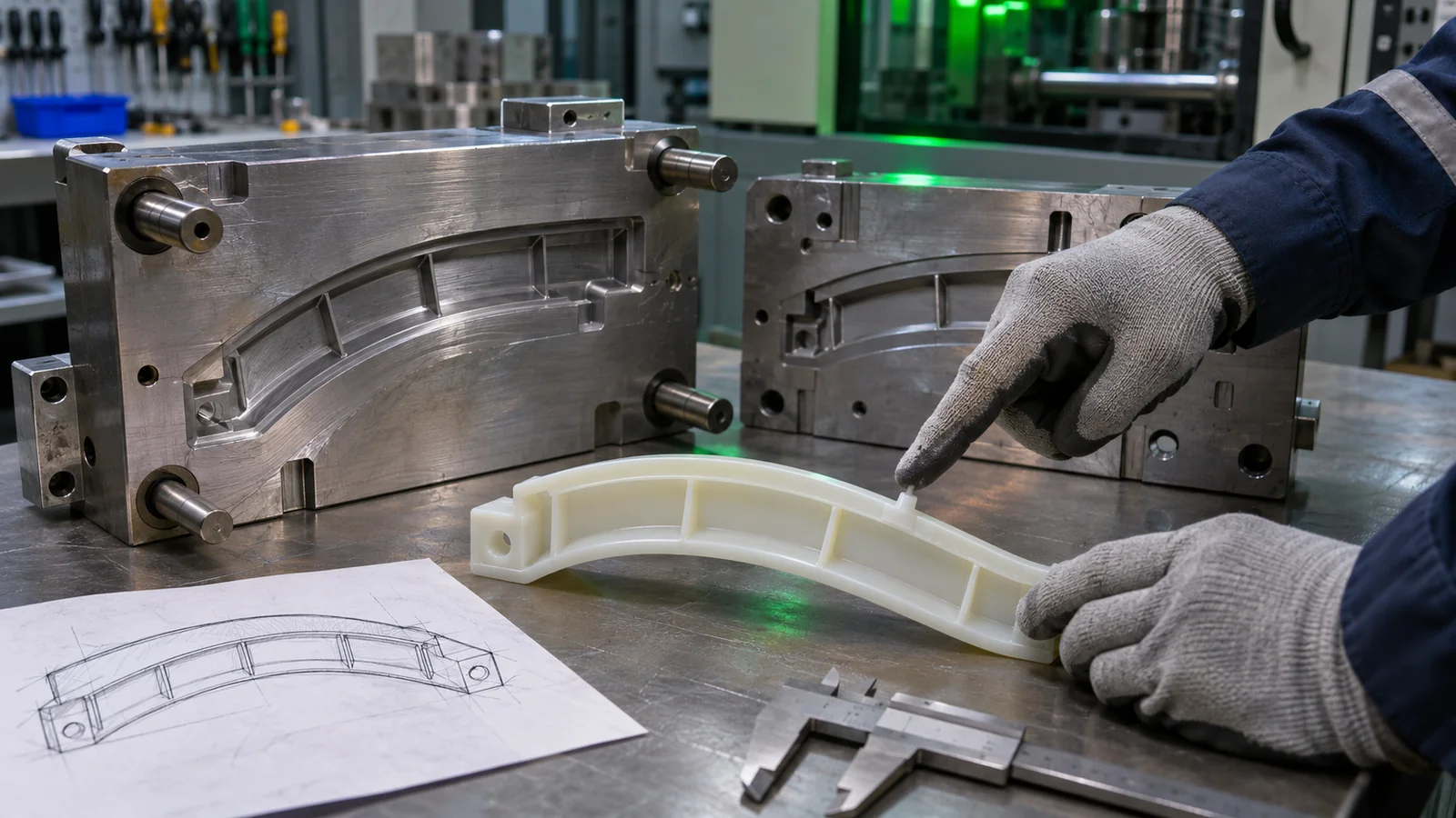
Draft and parting strategy matter because the component must release without damage to the contact track or mounting details. Ejector locations should avoid critical surfaces where possible, and gate vestige or flash limits should be documented when they affect fit or movement. If the guide is machined after molding, define which faces or holes receive that operation and how the part is located. The complete route may therefore include molding, trimming, secondary machining, cleaning, and inspection. Each operation needs a clear handoff so a later step does not erase the datum established earlier.
Inspect the geometry that controls fit and travel
Inspection should connect the mounting interface to the working track. A coordinate report may include hole positions, seating pads, profile sections, and the relevant relationship between those features. Choose measurement points from the drawing and functional question rather than generating a dense data cloud with no stated acceptance logic. For a long curve, sectional measurements can help show where a deviation occurs, but the sampling plan must match the specified profile requirement and the inspection method should be agreed in advance.
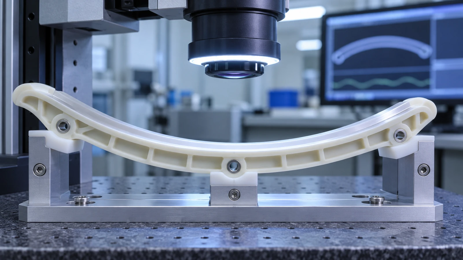
Also define how the part is conditioned and supported during measurement. Polymer parts can respond to environmental and fixture conditions, and a clamped component may appear more conforming than its free-state shape. Record the part identification, drawing revision, material condition if specified, measurement method, and any controlled restraint. If a visual edge, flash, or gate mark is limited by the design, define the acceptance zone. These records allow the engineering team to distinguish a geometry issue from a measurement setup issue without assigning unsupported root causes.
What belongs in a timing-guide RFQ?
Provide a controlled 2D drawing and 3D model, the specified resin and condition, annual or release quantities, prototype or production stage, color or surface requirements if applicable, and the inspection evidence expected. Identify the chain-contact region, installation datums, critical clearances, and any interfaces that must be held to a mating component. If the material or tool design is not final, say which items are open so quotations do not make different assumptions. A clear automotive timing chain guide manufacturing RFQ also identifies whether the sample should represent molded material behavior or only a machined geometry study.
Ask the supplier to return technical questions with the quote: unclear profile controls, inaccessible inspection points, uncertain parting-line locations, or a secondary operation that could affect the working path. A useful proposal separates tooling, sample, machining, and inspection scope where relevant. It should also state which values come from the customer drawing and which process details need approval. This makes the review concrete while keeping design authority and performance validation with the responsible vehicle program.
For broader vehicle component context, see the automotive manufacturing processes overview; the part drawing still controls the material, geometry, and acceptance criteria discussed here.
Frequently asked questions
Can a machined guide prototype validate the production molded part?
It can help check envelope, mounting, selected dimensions, and assembly clearance. It does not reproduce every molding effect or establish service performance. Define the intended learning question before choosing the route.
Should the guide contact profile be measured across its full length?
The drawing and functional design determine the required method and sampling. A supplier should not invent a profile tolerance; request the defined characteristic and agree how the report will represent it.
Can a supplier choose a replacement resin for easier molding?
Material substitution requires approval from the design authority. Processing advice can inform the discussion, but the program specification and validation plan govern the accepted material.

