


A camshaft is a sequence of surfaces organized around a rotating axis. Journals support rotation, lobes define valve motion, and timing features relate the shaft to the rest of the engine. A part can meet individual diameter checks and still miss its purpose if lobe phase, journal alignment, runout, or end-feature relationships drift from the released definition. For an engineering or purchasing team, the key is to translate the design intent into a machining and inspection plan before the first chip is cut.
This article focuses on custom automotive camshaft machining for prototype and development work. It explains how to structure the drawing review, decide what must be held in common setups, and communicate material and verification requirements. It is not a substitute for an engine design specification. Lobe profiles, timing, hardness, surface treatment, lubrication assumptions, and acceptance limits must come from the program owner.
Contents
- Read the shaft as a linked geometry system
- Turn the model into an inspectable definition
- Choose a blank that matches the development question
- Separate roughing, reference-making, and finishing
- Verify phase and form with a declared method
- Give the supplier a controlled handoff
- Frequently asked questions
Read the shaft as a linked geometry system
Begin with the axis and then map the features that depend on it. Journals may establish the rotational support; lobes sit at specified axial stations and angular positions; a nose, keyway, gear, trigger wheel, or timing interface may set clocking. The ends may include threads, centers, pilots, or oil-related features. Which of these appear depends on the design, so the supplier should not infer a universal camshaft architecture from the component name.
Build a simple feature map from the released drawing: identify the primary rotational axis, the lobe sequence, each lobe’s axial location and phase reference, journal spans, and the timing datum. Mark features that are functional contacts separately from reliefs and nonfunctional transitions. This map exposes an important question early: which dimensions control the relationship among lobes, journals, and timing features, and which can be inspected independently?

Form matters as much as nominal size. A lobe may be defined by a profile or coordinate data rather than a single radius. A journal may have specified cylindricity or finish. A timing slot may be angularly positioned from an agreed datum. If the drawing gives a profile but not its coordinate origin or orientation, the measurement can be ambiguous even when the CAD model appears complete.
Turn the model into an inspectable definition
A solid model communicates shape; the drawing or controlled product definition communicates acceptance. Confirm units, revision, material form, heat-treatment state, coating or surface treatment, and any critical-to-function characteristics. Make clear whether lobe geometry is accepted in the as-machined state, after heat treatment, or after finishing. A measurement taken at the wrong stage may not answer the engineering question.
Use a datum scheme that reflects how the shaft is supported and clocked. The rotational axis may be established by selected journals or centers; the axial origin may come from an end face; the clocking reference may be a key, slot, gear feature, or defined lobe. The design authority should decide the datum strategy and tolerances. A supplier can identify a setup conflict or propose a more repeatable inspection sequence, but changes to functional references need approval.
Separate profile requirements from general notes. Specify which lobes are measured, what coordinate system applies, how phase is reported, and what sampling or reporting convention the program accepts. Avoid a note such as “inspect cam lobes” without saying which lobe stations and characteristics matter. For a changing design, identify the controlling model and drawing revision so that toolpaths and reports refer to the same geometry.
Choose a blank that matches the development question
Camshafts may be produced through different starting forms and process chains. A prototype machined from bar or billet can support geometric evaluation when that route is acceptable to the design team. A production blank may be cast, forged, assembled, or otherwise prepared according to a program-specific route. These paths can differ in material flow, residual stress, heat-treatment response, and available stock. A machined prototype therefore answers only the questions its material and process can represent.
When comparing routes, look beyond machine time. Ask what the blank specification says, how much material must be removed, whether slender sections are prone to movement, and when the program expects hardened or finished surfaces. A low-quantity prototype may prioritize iteration speed and access to the geometry; a later production process may require dedicated tooling or different controls. Record the transition criteria instead of assuming one route automatically qualifies the next.
Material choice is likewise drawing-led. Steel grades and conditions vary in machinability and response to heat treatment. The correct source and condition must be stated rather than guessed from engine application. For general context on custom automotive components and CNC process planning, see the automotive CNC machining overview. It does not replace the camshaft specification, material certificate requirements, or process approval defined by the customer.
Separate roughing, reference-making, and finishing
A practical process plan distinguishes three aims: remove bulk stock without destabilizing the blank, create references that can be reused, and finish the surfaces that control function. On a long shaft, workholding must resist cutting forces without introducing excessive deflection. Supporting the part at suitable locations and planning support changes are important considerations, but exact fixtures depend on length, diameter, blank condition, and machine access.
Roughing all lobes to near size before creating a stable reference may leave the part vulnerable to movement. Conversely, finishing one lobe completely before the rest of the shaft is stabilized can make later stock removal affect its relationship. A staged sequence can reserve finishing allowance, re-establish the axis after roughing, and finish linked features from consistent references. Whether this is needed depends on the component geometry and material condition; it should be decided from the actual drawing and blank.
Some features may suit turning, while lobes and timing geometry may require milling, grinding, or a dedicated profile process. The route depends on the specified profile, surface condition, material state, quantity, and acceptance method. Tornitura CNC is relevant to cylindrical shaft features, but a turned journal operation does not establish lobe form or timing phase by itself. The quote should identify included operations and any outsourced finishing or heat treatment.
Verify phase and form with a declared method
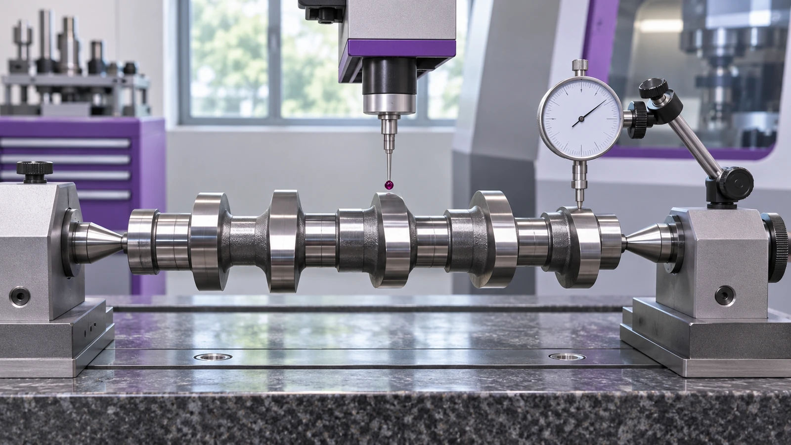
A useful inspection plan pairs each feature with an acceptance question and method. Journal diameter and roundness may be checked differently from lobe lift or profile. Lobe phase needs a clocking reference. Axial location needs an origin. Runout needs a defined support condition and measurement setup. Surface finish needs a stated location and evaluation direction. The customer’s drawing and quality plan set the requirements; the report should identify how the part was held and what was actually measured.
| Feature group | Question to resolve | Handoff detail |
|---|---|---|
| Journals | Which surfaces define the rotational axis? | Datum references, size and finish requirements |
| Lobes | How are profile, lift, station and phase defined? | Coordinate frame, selected stations and reporting convention |
| Timing features | What establishes angular orientation? | Clocking datum and relationship to the lobe sequence |
| End features | Which face or pilot controls axial position? | Origin, fit and inspection condition |
A table like this is a review aid, not a substitute for numerical limits. If the project uses a functional gauge, define what it simulates and which characteristics it can or cannot verify. For a prototype, agree whether the report covers all features, a selected set, or only the geometry needed for a specific build event. Keep part identification, revision, material records, and inspection results connected.
Give the supplier a controlled handoff
Provide the drawing and model, quantity, revision, material grade and condition, blank form, heat-treatment and finishing scope, critical characteristics, inspection report requirements, and target delivery stage. If the shaft will be balanced or assembled later, state whether those operations are outside the machining quote. Note any customer-supplied tooling or test fixture, and identify who owns calibration or acceptance decisions.
For design iterations, show what changed: lobe profile, lobe phase, journal span, timing slot, end configuration, or material allowance. A revision table or change summary helps the supplier update programming and inspection rather than reusing an old setup. Prototype orders should also state the build purpose—packaging, valve-train fit, timing verification, or another engineering question—without implying that a dimensional prototype proves engine endurance.
When a team needs a custom part for a development build, Jucheng’s automotive prototyping service can be reviewed alongside the machining requirements. Confirm the actual material, operation, inspection records, and limits included in each quote. Clear scope makes it easier to compare suppliers on the same definition.
Frequently asked questions
Can a CNC-machined prototype validate a production camshaft?
It can validate defined geometry or assembly questions if the prototype material and process are suitable for those questions. It does not automatically represent a production blank, heat-treatment route, surface process, or engine-level durability test.
Why is lobe phase separate from lobe dimensions?
A lobe can meet its local profile while being clocked incorrectly relative to the shaft’s timing datum or other lobes. The drawing and inspection plan should define both shape and angular relationship.
Should every journal and lobe be reported?
The required scope depends on the program’s acceptance plan. State the characteristics and sampling expectations explicitly so that the report is neither incomplete nor padded with measurements that do not support the design decision.
Camshaft machining becomes more predictable when the drawing connects the rotational axis, lobe profile, phase, and timing references. That connection guides the process sequence and keeps inspection focused on the relationships the engine team actually needs to verify.

