


Closing a needle holder is easy to observe. Explaining why its jaws do not produce the intended grip requires a closer look at the complete mechanism. Jaw geometry, surface features, pivot clearance and handle closure interact. Inspecting each component in isolation can miss a problem that appears only after assembly.
Surgical needle holder manufacturing therefore needs a component plan and an assembly acceptance plan. This discussion covers conventional hand instruments for OEM development. It addresses manufacturing decisions, not clinical technique or the selection of an instrument for a procedure. The device owner must define the intended application and the corresponding validation requirements.
Follow the contact from the handles to the jaws
Start by drawing the mechanical path. The handles move around the joint, the ratchet retains a defined closure position, and the jaws contact the specified test object. A discrepancy anywhere along that path can alter the apparent gripping result. A visually closed instrument does not prove that the intended contact has formed.
Ask the designer to identify what the acceptance test represents. Is the project evaluating jaw alignment, retention, opening and closing behavior, or the relationship between successive ratchet positions? These are separate questions. One informal hand check should not be treated as a complete product acceptance method.
Record the configuration of the sample used for any comparison. Jaw length, tip form, handle geometry and insert design may differ between instruments that share a general product name. A supplier needs the controlled drawing and approved test definition rather than a photograph of a similar instrument.
This assembly perspective belongs within the broader medical device manufacturing processes review. It gives component machining, finishing and final inspection a common reference. It also helps distinguish a component supplier’s responsibilities from the device manufacturer’s verification and release responsibilities.
Separate solid jaws from insert-based construction
Decide whether the jaws are integral to the instrument or contain separately manufactured gripping inserts. Those routes require different drawings, process steps and inspection points. Neither construction can be specified adequately by calling the whole instrument stainless steel.
For integral jaws, the finished gripping pattern and supporting geometry are produced in the parent material. Material condition, cutting access and subsequent finishing must be considered together. Surface treatment should not round off or obscure a functional texture that the drawing requires.
For an insert-based design, define the insert, its seat and the approved attachment method. The joint between insert and body is part of the design, not a purchasing detail to resolve after machining. Attachment may influence local geometry, surface condition and the order of operations. The supplier should identify its proposed route for customer review rather than choose a joining process silently.
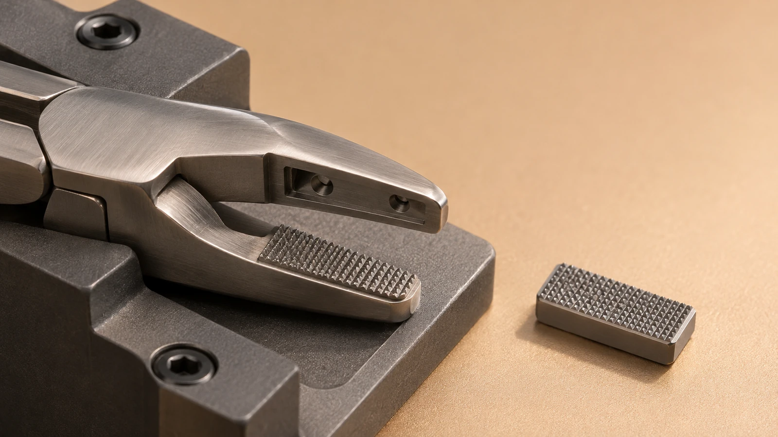
B. Braun describes needle holders with tungsten carbide inserts. That does not mean every design requires them, or that a generic carbide specification establishes equivalent performance. Insert grade, geometry, attachment and finished condition must follow the controlled specification. A substituted insert can change the behavior of the assembled instrument even when its outside dimensions match.
Jucheng’s la lavorazione dell'acciaio inossidabile service is relevant to instrument bodies and defined components. For a complete instrument project, the enquiry should separately identify insert sourcing, assembly, finishing and test responsibilities. This prevents a component quotation from being mistaken for a validated finished-device offer.
Resolve alignment before changing the gripping pattern
When a sample slips during a defined test, changing the jaw texture immediately may conceal the underlying problem. First inspect whether the jaws meet in the intended relationship. Uneven contact can result from jaw geometry, joint clearance, assembly variation or an incorrect test setup.
Inspect the joint in the specified condition. A component measured before assembly may not represent its installed relationship. Conversely, forcing an assembled instrument into a fixture can hide clearance or alignment behavior. Document how the instrument is supported and which closure position is used for each measurement.
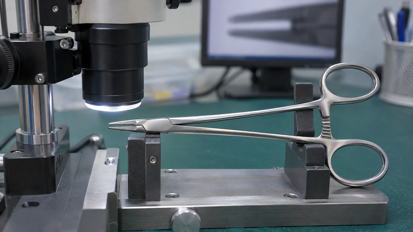
The ratchet deserves its own review. Engagement should be evaluated according to the approved drawing and acceptance method, including the relationship between engagement and jaw position. Do not assume that one extra ratchet step is a suitable way to correct a component discrepancy. The resulting load and motion may differ from the intended design.
Use the evidence to select the next investigation. If contact is uneven, examine alignment and the joint. If contact is correct but retention is inconsistent, examine the test object, surface condition and gripping features. If results differ after finishing, compare the relevant geometry and cleanliness before and after that operation.
| Observation | Manufacturing question | Useful evidence |
|---|---|---|
| Jaws contact on one side first | Are jaw and pivot relationships correct? | Defined alignment measurement and assembly condition |
| Closure differs between samples | Are joint clearance and ratchet relationships consistent? | Component records plus an agreed assembled check |
| Retention changes after finishing | Did texture, edge condition or contamination change? | Before-and-after observations using the same method |
| Repeated tests disagree | Is the test object and setup controlled? | Identified test pieces, fixture details and procedure revision |
Make the finishing sequence visible
Instrument appearance is only one output of finishing. Edge treatment, surface condition and preservation of functional features matter as well. The manufacturing plan should identify which surfaces may be polished and which dimensions or textures must remain controlled.
Il servizi di finitura superficiale discussion should include masking or protection where needed, access to recessed areas, and inspection after processing. A polished outside surface does not demonstrate that a joint or insert boundary has the required condition.
Material and heat-treatment requirements must be agreed before the route is finalized. A generic alloy name is insufficient when the drawing requires a particular grade, condition or treatment. Operations performed before and after treatment can have different implications for distortion and final adjustment.
Cleaning, packaging and any device-level reprocessing requirements also need a defined ownership boundary. A machining supplier’s handling and cleaning steps should not be described as validated sterilization. If the project requires evidence beyond component inspection, state the applicable requirement and who will generate and approve it.
Keep inspection records connected to the actual revision and lot. When a jaw feature changes, identify whether earlier samples remain suitable for comparison. Comparing a revised instrument against an unmarked old sample can turn a controlled development decision into an unexplained disagreement.
Use the first sample to close specific questions
A useful prototype order names the uncertainty it is intended to resolve. For one project, the question may be whether the jaw features can be manufactured and inspected. For another, it may be whether assembly variation remains within the customer’s defined requirements. These call for different sample and reporting plans.
Provide drawings for the body, joint, gripping features and any inserts, together with the assembly drawing. Include material specifications, approved finishes, the intended supply boundary and the acceptance methods. Identify dimensions that require discussion rather than leaving the supplier to infer importance from a tight tolerance alone.
Il prototyping service enquiry can then focus on machining access, feature measurement and practical assembly sequencing. This is where a manufacturing partner can add value: showing how a requirement will be made and checked, and identifying unresolved interfaces before the order expands.
Release the next stage only against the agreed evidence. A sample that looks right may still leave questions about repeatability, attachment or final inspection. Record what the sample demonstrates and what remains to be evaluated. That makes the next batch a controlled progression rather than a larger repetition of the same uncertainty.

