


A landing gear torque link is a compact part with a relationship-heavy geometry. Its arms connect through pivot pins, so the locations and orientations of the two pin interfaces matter together. If each bore is measured only for its local diameter, the report may miss the feature that controls how the link fits and articulates in the assembly: the relationship between the axes, end faces, and surrounding link geometry.
This article treats aircraft landing gear torque link machining as a part-specific manufacturing and inspection discussion. The existing aircraft landing gear components overview addresses the broader supplier handoff for landing gear parts; this page narrows the scope to the torque link’s pin interfaces and their machining logic. It is not maintenance guidance or a substitute for released aerospace design data, stress analysis, or program-specific quality requirements.
Contents
- Define the link’s role and interfaces
- Make both pin axes part of one datum strategy
- Choose a blank and process route for the geometry
- Keep setups from breaking the axis relationship
- Verify bore geometry in the defined condition
- Send a complete manufacturing handoff
- Frequently asked questions
Define the link’s role and interfaces
Start with the assembly drawing and identify the torque link’s mating parts, pivot pins, bushings, spacers, and retention features. The geometry may include two clevis-like ends, paired ears, a central web, or another configuration. Do not assume that every design uses identical end forms. Mark which surfaces locate against hardware, which bores accept pins or bushings, and which areas are clearance or weight-management features.
The link’s function in the assembly gives context, but does not define acceptance by itself. Loads, motion envelope, allowable play, material, fatigue criteria, and surface requirements must be supplied by the responsible design authority. A supplier can interpret the drawing and raise manufacturability questions; it should not derive structural margins or functional limits from a nominal CAD model.
For a development build, state what the part is intended to demonstrate. It may support a packaging review, a pin-fit check, an assembly sequence trial, or a defined engineering test. A machined prototype that demonstrates fit does not on its own establish strength, fatigue life, landing performance, or airworthiness.
Make both pin axes part of one datum strategy
The most useful early review often starts with the two pin interfaces. Are the axes parallel, coplanar, offset, or intentionally angled? Which end establishes the primary location? Is an end face used to control axial position? Does a bushing installation alter the inspection stage? The released drawing should answer these questions through datums and tolerances rather than leaving the supplier to choose whichever bore is easiest to reference.
A common datum frame can make the relationship inspectable. Depending on design, the frame may use a primary mounting face, a first pin axis, and a secondary face or feature to clock the link. The actual scheme must reflect how the part is located in the assembly. If each bore is dimensioned from a different local face, a part may pass individual checks while the two pivots do not align as intended.
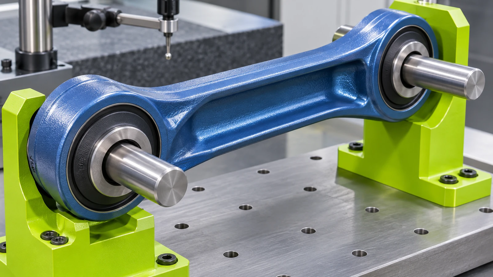
Separate functional control from overall contour. The pin axes, bushing seats, retention features, and any mating faces may govern fit. External surfaces may be less critical unless they establish clearance, load transfer, or inspection references. This distinction can prevent over-tolerancing and help procurement compare quotes on a meaningful basis.
Choose a blank and process route for the geometry
Torque links can be designed for different starting forms and production routes. A prototype may be machined from billet or from a supplied near-net blank; a later program may use a different forming or stock-preparation route. Selection depends on drawing requirements, part size, material specification, quantity, and the engineering question. A route suitable for geometry iteration may not represent production material flow, heat-treatment response, or validated process controls.
Look at the ratio between stock envelope and final geometry, the thickness of the link arms, the depth of the bores, and tool access to internal corners. A large amount of asymmetric stock removal can affect stability. A near-net blank can reduce machining volume but introduces blank-shape and allowance considerations. The quote request should identify the supplied blank or state whether the supplier is expected to source it.
Material is drawing-led. Some designs specify high-strength steels, while others may call for different alloys or product forms. Grade, condition, heat treatment, source restrictions, and traceability requirements should be stated. Jucheng’s high-tensile steel machining reference provides general material context for steel components, but cannot determine the approved landing-gear material for a specific program. The aerospace CNC machining overview provides a wider manufacturing context, not a certification or qualification statement.
Keep setups from breaking the axis relationship
Machining order should preserve how the two pin interfaces relate. One approach may rough the outside and web, establish stable datums, then finish both bores in a common setup if access allows. Another geometry may need separate operations because the arms obstruct the tool or fixture. When the part must be reoriented, define how the second setup recovers the first axis or datum frame. The right sequence depends on the drawing, machine access, stock condition, and required inspection.
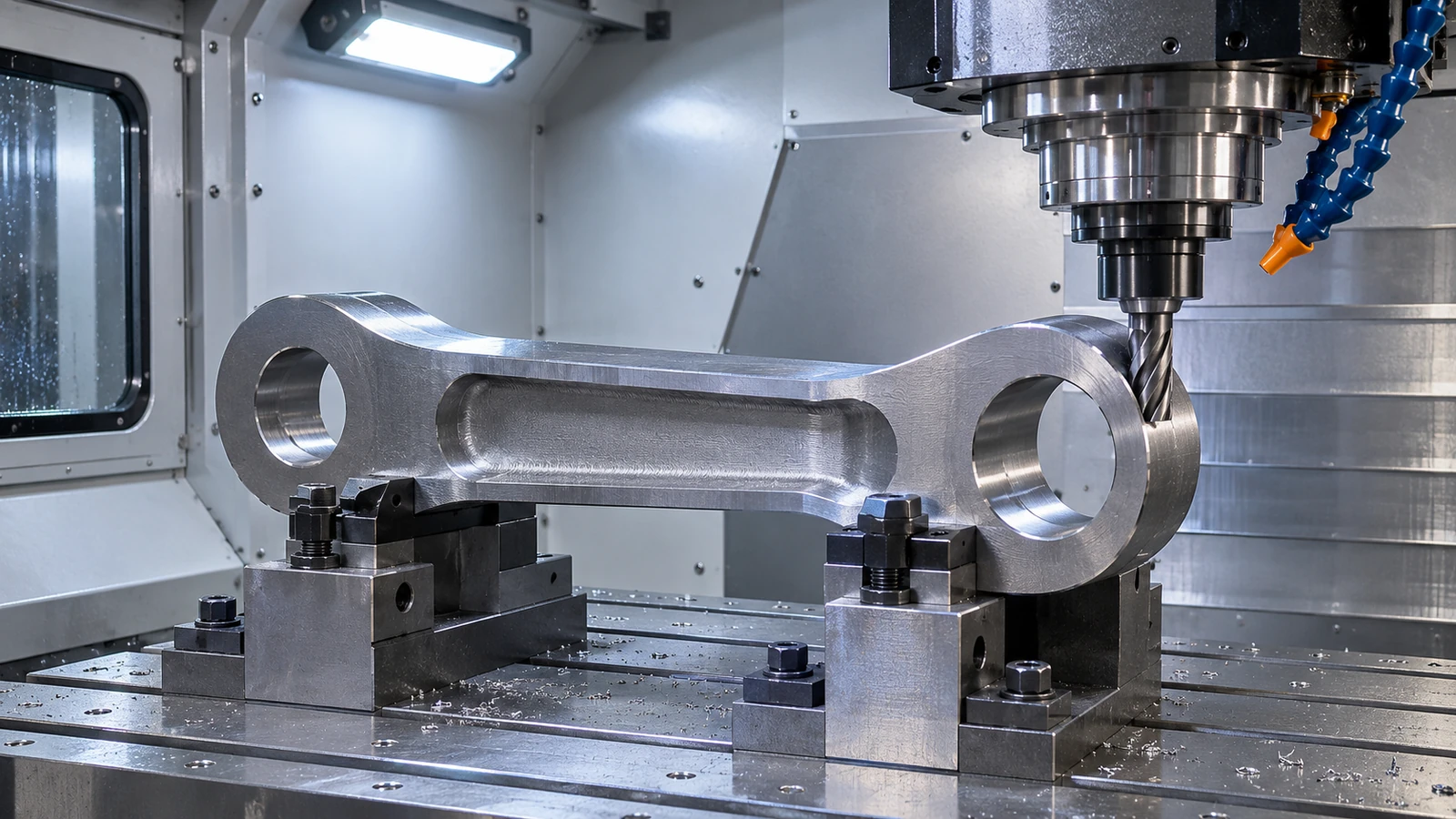
Workholding needs to support the component without deflecting the ears or distorting thin webs. Clamping force should be directed through supported regions where practical. If the blank is heat treated or has a process condition that can move during material removal, the supplier and customer may need to agree on roughing allowance, rest periods, intermediate checks, and the point at which final bores are cut. These are planning questions, not a universal recipe.
Consider tool reach and chip evacuation in deep bores or internal reliefs. A rough bore and a final bore may use different strategies; a bushing seat may require a controlled finish; cross-holes may need deburring or access verification. State the edge condition and surface requirements for functional areas. Avoid adding polishing or coating assumptions not present in the controlled definition.
Verify bore geometry in the defined condition
Inspection should evaluate more than bore diameters. Depending on the drawing, it may need to relate each axis to the datum frame, check the relationship between the axes, establish true position, evaluate bore form, and verify any bushing seat or retention feature. A coordinate-measuring system, dedicated fixture, or gauge can be appropriate for different characteristics. The accepted method and measurement condition must be stated in the quality plan.
Clarify whether the link is measured free-state, held in a fixture, or after bushings or other hardware are installed. A fixture may reproduce an assembly reference but cannot prove every system-level requirement. If a representative pin or gauge is used, identify its dimensions, revision, and the question it is intended to answer. Measurement access at the bore ends and around shoulders should be checked when the report plan is developed.
For first-article or prototype reporting, tie each result to the part number, revision, material lot or required traceability record, process stage, and inspection equipment where required. Separate dimensional acceptance from proof testing, fatigue testing, or aircraft-level qualification. A supplier should report only checks actually completed and within the agreed scope.
Send a complete manufacturing handoff
A useful RFQ includes the released drawing and model, quantity, revision, material grade and condition, blank form, heat-treatment and finish requirements, critical characteristics, inspection-report scope, and any required records. Include the assembly context needed to understand the datums, but identify the part drawing as the acceptance authority. Note whether bushings are supplied separately or included and whether installation is part of the quote.
Call out changes between revisions, especially bore spacing, axis angle, ear thickness, relief shape, and bushing or pin interface. These can change both machining and inspection. If multiple variants are ordered, provide a table that maps each part number to model revision, material, quantity, and report requirement. That reduces the risk of a correct part being associated with the wrong configuration.
State the intended prototype or production stage without implying a qualification status. If the part is needed for a fit review, say so. If it must follow a specific approved process, provide the applicable requirement and supplier controls. Clear scope supports a meaningful quote and a controlled review between design, procurement, and manufacturing.
Frequently asked questions
Why are both pin axes important?
The link connects two pivot interfaces. Their relationship can affect how the part assembles and articulates, so inspection should use the drawing’s common datum frame rather than check each bore only as an isolated hole.
Can billet machining be used for a torque-link prototype?
It may be suitable for a defined development question when the material and route are accepted by the design team. It does not automatically represent a later forging or other production route.
Does a first-article report qualify the landing gear assembly?
No. It documents the part characteristics included in the agreed inspection scope. Assembly performance and program qualification require separate engineering evidence.
Torque-link manufacturing is easiest to control when the two pivot interfaces are defined as one geometric system. Clear datums, a route suited to the blank, and an inspection plan tied to the assembly question give the supplier a practical basis for producing and reporting a custom component.

