


A landing gear part is not production-ready just because its solid model is complete. It must fit an assembly, carry defined loads through controlled interfaces, remain inspectable, and arrive with the records the buyer actually requires. A drawing that leaves any of those decisions implicit can turn a straightforward prototype into a chain of clarification, rework and delayed acceptance.
This guide looks at aircraft landing gear components from a manufacturing handoff perspective. It is intended for product engineers and procurement teams reviewing custom components, not as a maintenance manual or a substitute for approved design data. The central question is practical: what should be resolved before a supplier is asked to quote or machine a part?
- Define the job each component performs
- Resolve interfaces before tolerances multiply
- Choose a manufacturing route around the feature set
- Keep material and process records connected
- Make inspection possible, not merely requested
- Build a release package the supplier can quote
- Frequently asked questions
Define the job each component performs
Landing gear is an assembly, not a single part category. A project may include load-bearing members, axle or pivot features, brackets, covers, links, housings and interfaces for sensors, lines or actuation. These components do not share one manufacturing logic. Before selecting a process, identify the part’s role, its mating neighbors and the characteristics that affect the assembly’s function.
Start with the controlled drawing and the assembly context. Which surfaces locate the part? Which holes carry fasteners or pins? Which axes must align with other components? Which areas are clearance surfaces, and which are functional contact surfaces? A model can show nominal geometry, but the drawing or product definition must state how the finished part is accepted.
Separating functional from nonfunctional features is an important cost and quality decision. A locating bore may need a defined size and position relationship; an exterior relief may not need the same precision. When every dimension is treated as equally critical, suppliers have less room to select an efficient process and inspectors have a less useful acceptance plan.
For an early prototype, record what the part is intended to prove. It may validate packaging, assembly access, interface fit or a tooling concept. A prototype that checks envelope alone should not be presented as proof of structural performance. Keeping the verification objective explicit prevents a visual fit check from being mistaken for qualification evidence.
Resolve interfaces before tolerances multiply
Interface errors often appear far from the feature where the drawing ambiguity began. A hole may be correctly machined to its local size but still fail to align with a mating bracket because the datum scheme does not control the relationship that matters. Review the component in the assembly and define datums from functional contacts rather than from whichever faces are easiest to dimension.
For fastener patterns, identify the controlling pattern, position requirements, edge distances and any orientation or clocking constraint. For a pivot, bearing or bushing interface, define the intended fit and the measurement condition. For mating faces, state the relevant flatness, parallelism or perpendicularity only where it controls assembly or function. The applicable design authority must set the actual limits.

A tolerance stack review is useful when several parts jointly establish a position or gap. It helps separate the variation that the individual part drawing can control from the variation that belongs to the assembly or system. This is particularly valuable before a supplier quote, because a late change to datum references can force a different workholding or inspection strategy.
Use section views and detail callouts where a critical interface is hidden in the overall view. Clarify whether dimensions are measured before or after a specified coating or finish. If a fastener, insert, bushing or seal is supplied separately, identify the boundary of supply so that the quote does not silently assume an unlisted assembly operation.
Choose a manufacturing route around the feature set
The best route depends on geometry, quantity, material condition, required evidence and project stage. A machined component can be practical when the design needs precise interfaces or the order is a prototype or limited run. A formed or fabricated component may suit a different geometry. A casting, forging or other near-net process may be relevant to a production design, but it brings its own tooling, process-control and approval considerations. The product definition and approved supplier scope determine which options are acceptable.
| Design situation | Questions to resolve | Manufacturing handoff focus |
|---|---|---|
| Complex interfaces or low initial quantity | Can critical faces and bores be reached in a stable setup? | Datums, workholding access and inspection plan |
| Thin formed geometry or integrated flanges | Are bend sequence, reliefs and mating clearances defined? | Forming assumptions and post-form feature controls |
| Near-net production concept | What tooling, process qualification and finishing steps are required? | Supplier scope, material condition and change control |
| Prototype for fit or packaging | Which characteristics are being demonstrated, and which are not? | Explicit verification objective and limitations |
The point is not to select a route from a generic chart. It is to make the tradeoffs visible early. A design may be easy to machine but expensive to inspect; another may reduce material removal but require tooling or process approvals that do not suit a one-off prototype. Ask suppliers to identify manufacturability risks against the same revision and the same acceptance requirements.
For programs spanning several methods, the wider aerospace manufacturing and prototyping landscape can help teams frame how components move from design evidence to a suitable production route. The final decision must still follow the released engineering definition and project controls.
Keep material and process records connected
Material is more than an alloy name on a purchase request. The released definition may include product form, temper or condition, specification, source restrictions and required traceability. If a component has a specified heat treatment, coating or other special process, identify it clearly and state which records are part of acceptance. Do not rely on a supplier to infer a requirement from the application alone.
When a finish changes a critical dimension, make the measurement sequence explicit. State whether the controlled dimension applies before treatment, after treatment or at a defined stage. For mating interfaces, consider how masking, coating build or local finishing affects fit. These are drawing and procurement decisions, not details to resolve after production has started.
Revision control must travel with the material and inspection evidence. A record that cannot be tied to the purchase order, drawing revision and delivered part is difficult to use during receiving or later review. Specify the identifiers needed on documents and labels, while avoiding unsupported assumptions about which certifications or records are automatically included.
If the buyer is considering an alternate material or process, treat that as a formal engineering change. Similar names do not establish equivalence. Any substitution should be evaluated and approved by the responsible design authority before it enters the manufacturing route.
Make inspection possible, not merely requested
Inspection requirements should be measurable and linked to function. Identify the characteristics that control fit, alignment, contact and interchangeability, then specify how they will be verified. A note that says “inspect all dimensions” is not a substitute for defining acceptance limits, datums, sampling expectations or documentation for the features that matter most.
Check whether the chosen measurement method can reach the feature without disturbing the part. Deep bores, internal shoulders, thin walls and compound angles may require a planned setup or a different instrument. If the feature cannot be measured directly, agree on an appropriate verification approach with the customer or design authority before machining begins.
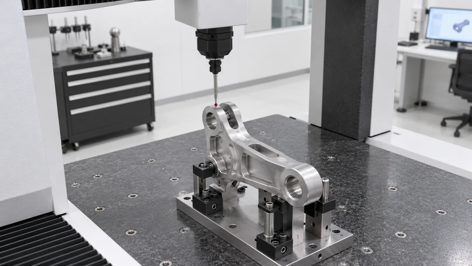
A first-article inspection can help establish that a new process route and drawing interpretation produce the intended part. For it to be useful, the report should identify the part number, revision, material identity and the characteristics actually measured. The term “first article” does not by itself define the scope of inspection; the purchase requirements must do that.
Protect finished surfaces during subsequent operations and handling. A part can pass dimensional inspection and still be damaged before shipment if the packaging or work sequence allows contact at a critical interface. Define protection requirements where they are necessary, and ensure the receiving inspection can distinguish shipping damage from a manufacturing nonconformance.
Build a release package the supplier can quote
A clear RFQ package normally brings together the controlled 2D drawing, current 3D model, revision, quantity, material and condition, finish requirements, inspection expectations, traceability needs and requested delivery assumptions. Include assembly views or interface drawings where they clarify how the component is used. State the intended scope: machining only, finishing, inspection records, assembly, or another defined set of operations.
Separate mandatory requirements from questions for supplier feedback. A manufacturer can suggest a more practical tool path, workholding orientation or inspection sequence, but the suggestion does not change the design definition until it is reviewed and approved. This boundary lets engineering benefit from manufacturing input without allowing an informal quote note to become an uncontrolled design change.
Before release, run a short cross-functional review:
- Does the drawing identify functional datums and mating interfaces?
- Are tolerances concentrated on characteristics that affect fit or function?
- Can the proposed route access and inspect the critical features?
- Are material condition, finish and records explicitly stated?
- Is the prototype objective distinct from qualification or production acceptance?
- Can the receiving team match documents to the delivered revision?
This preparation makes supplier feedback more specific and the quotation easier to compare. It also gives the team a traceable basis for resolving questions if the design changes after initial prototypes. A successful manufacturing handoff is not a promise that every risk has disappeared; it is a clear record of what is controlled, what is being verified and who approves a change.
Frequently asked questions
Can a prototype landing gear part be treated as flight-ready?
Not by default. Prototype status, material, process, inspection scope and intended use must be defined by the responsible engineering and approval authorities. A part built for packaging or fit validation is not evidence of structural qualification.
Which landing gear component features deserve the closest drawing review?
Focus on interfaces that locate, pivot, fasten, contact or align with other components, along with any surfaces or dimensions explicitly identified as critical by the design authority. The actual controls depend on the assembly and released requirements.
What should an RFQ include?
Provide the current drawing and model, revision, material and condition, quantity, finishing scope, acceptance criteria, documentation needs and intended use of the prototype or production parts. Identify any open design questions rather than hiding them in general notes.

