


Aircraft nacelle components form the aerodynamic and structural enclosure around a propulsion system, while also carrying interfaces for adjacent aircraft structures and systems. A nacelle is not one simple shell: panels, lips, doors, pylons, acoustic treatments, brackets, and service interfaces can each follow different manufacturing routes. For a supplier, the first task is to define which component is in scope and how it mates with the larger nacelle assembly.
That scope matters because published information often describes complete nacelle programs, while an RFQ may cover only a machined fitting, formed panel, prototype duct, or assembly fixture. This guide narrows the discussion to component-level manufacturing planning, interface control, and prototype handoff.
Contents
- Separate the nacelle system from the part being sourced
- Map boundaries, interfaces, and access
- Match each component to its process
- Assembly fit is a manufacturing output
- Prototype work should isolate one uncertainty
- What to include in the component RFQ
- Frequently asked questions
Separate the nacelle system from the part being sourced
A nacelle is the enclosure and supporting structure associated with an aircraft propulsion installation. It may include inlet structures, fan cowl panels, thrust-reverser structures, exhaust-area components, pylons, acoustic liners, access doors, and local hardware. The configuration varies by aircraft and engine program, so a generic component list should not be used as a substitute for the current product definition.
Before quoting, identify the exact part number or development identifier, the assembly level, and whether the supplier is expected to deliver an individual part or a checked subassembly. Clarify whether drawings, models, tooling data, and finish requirements are controlled or preliminary. Without that boundary, a supplier may quote a simple detail part while the buyer expects interface verification across an assembly.
Place the work in the broader Aviation and Aerospace parts manufacturing context, but keep the quote specific to the actual component and revision.
Map boundaries, interfaces, and access
Components around an engine installation can meet curved surfaces, adjacent panels, structural frames, hinges, latches, seals, and service openings. A surface that looks cosmetic may control aerodynamic continuity or a seal gap. A hole pattern may locate a door or bracket. Identify which interfaces are functional and which are allowed to absorb variation through an approved fit-up process.
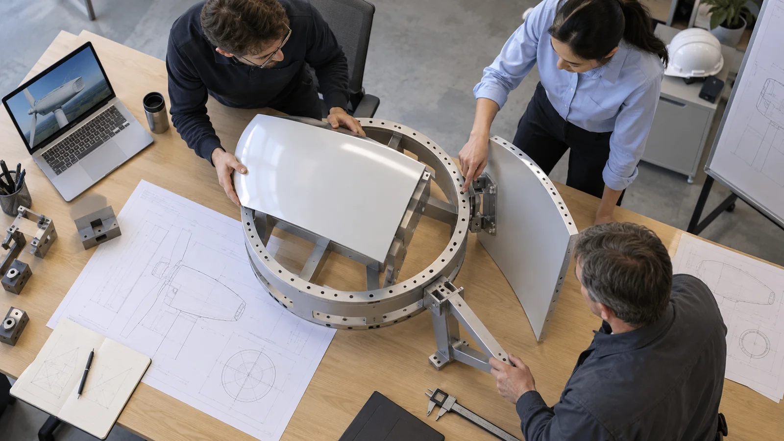
Access matters in both manufacturing and inspection. A formed panel may be easy to shape but difficult to measure after a flange is closed. A bracket may be straightforward to machine but hard to inspect once attached. A small access opening can determine whether an internal fastener or surface can be reached without rework.
At design review, mark the boundary conditions on a section view or assembly model: adjacent parts, fastener direction, tool access, sealing surfaces, and inspection sight lines. This turns a vague “nacelle component” request into a manufacturable scope with an agreed handoff.
Match each component to its process
Different nacelle parts call for different process families. Sheet metal forming can be relevant to panels and ducts. CNC machining can suit brackets, interfaces, and features requiring controlled geometry. Additive manufacturing may help evaluate a prototype bracket or complex duct concept, subject to the intended use and material requirements. Joining and assembly may then connect these parts into a larger unit.
| Component type | Process questions | Potential planning risk |
|---|---|---|
| Curved panel or cowl detail | How are forming allowance, springback, edge trimming, and interface datums controlled? | Panel contour matches locally but misses the assembly gap or sealing boundary |
| Machined bracket or fitting | Which faces locate the part, and can the hole pattern be inspected from the same datum? | Mounting points are individually correct but do not align in assembly |
| Prototype duct or complex shape | Is the sample for packaging, fit, flow study, or production-process evaluation? | A development article is mistaken for a qualified production part |
Where sheet construction is appropriate, review the di fabbricazione della lamiera against the part’s geometry and fit requirements. For a geometry-only mock-up, an aerospace 3D printing prototype route may be considered when it answers a defined development question.
The process table is a scoping aid, not a certification matrix. Material, temperature exposure, acoustic function, joining details, and program requirements can change what is acceptable.
Assembly fit is a manufacturing output
Component quality is not limited to the individual part drawing. Nacelle subassemblies often depend on the relationships among panels, hinges, latches, doors, and support points. A part can pass its own dimensional inspection and still create a difficult assembly if the datum transfer between part and fixture is poorly defined.

Use a fit check that references the same interfaces as the assembly drawing. Record which features are inspected on the loose component and which are verified after joining or installation. If a gap is controlled at the assembly level, define how it is measured, where the assembly is supported, and what condition is acceptable. Do not let informal hand fitting conceal a recurring process issue.
Change control is equally important. A small panel contour update can affect a neighboring bracket or seal. The buyer should identify affected interfaces and ask the supplier to state whether the change alters programming, tooling, inspection, or material already in process.
Prototype work should isolate one uncertainty
A prototype can answer questions about packaging, panel access, fastener reach, assembly order, tool clearance, or visual geometry. It cannot answer every question at once. A polymer mock-up may confirm envelope and access but does not demonstrate the thermal, acoustic, or mechanical behavior of a final material. A machined metal prototype may test a mounting interface without proving the completed nacelle system.
Write the objective on the request: what will be checked, what material or process is representative, what deviations are allowed, and what decision follows the test. If the sample is non-flight or non-production representative, mark that status in the traveler and inspection record.
What to include in the component RFQ
Provide the current drawing and model revision, component identity, assembly context, material and condition, quantity, finish, joining requirements, interface characteristics, inspection records, and delivery packaging expectations. Include the surfaces that control fit or sealing and identify whether the part is a prototype, development article, or production-intent component.
Ask the supplier to list process assumptions and open questions. Examples include forming allowance, machining stock, tool access, fixture location, assembly check method, and features that cannot be inspected after integration. Resolve these before purchase order release when they affect acceptance.
A quote should also distinguish included operations from customer-provided steps. That avoids assuming that a part supplier is responsible for system integration, certification, or performance testing when the scope only covers a component.
Frequently asked questions
Are aircraft nacelle components all made by one process?
No. Panels, brackets, ducts, liners, and fittings can use different materials and processes. The component drawing and assembly role determine the route.
Can a prototype nacelle panel be made from a different material?
Sometimes, if the goal is limited to geometry or packaging and the difference is clearly recorded. A substitute material does not prove final thermal, acoustic, or structural performance.
What is the most important information for a nacelle component quote?
The controlled component definition, assembly interfaces, material, quantity, finish, acceptance characteristics, and intended use of the article are central. Open assumptions should be recorded before work begins.
Does a component inspection prove the complete nacelle assembly is acceptable?
No. A component report addresses the inspected part and listed characteristics. Assembly-level fit or performance requires its own defined verification.
Nacelle component manufacturing becomes easier to control when the buyer defines the system boundary, interface datums, and intended evidence before selecting a route. That keeps a prototype, a detail part, and a complete nacelle assembly from being treated as the same deliverable.

