


Define the chamber’s job before its shape
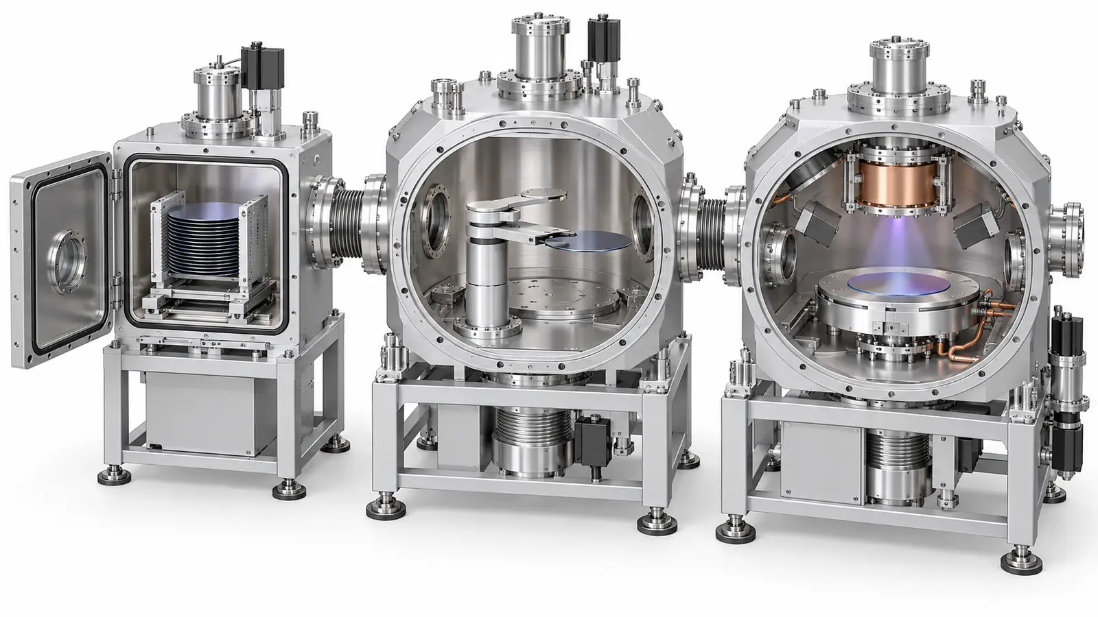
A load lock, a wafer-transfer chamber and a process chamber have different jobs, even when their external dimensions look similar. A load lock repeatedly brings a small volume from atmosphere to a transfer condition. A transfer chamber protects substrates while allowing robot motion. A process chamber must also accommodate the chemistry, thermal conditions and physical arrangement that create or remove a film.
That distinction changes the drawing. A load lock may prioritize evacuation time and repeated door operation; a transfer module needs an unobstructed wafer path; a deposition chamber may need removable shields and controlled relationships between a source, substrate and ports. Applied Materials describes high-vacuum integration as an important part of its semiconductor PVD platforms. This establishes the application context, not a universal pressure specification for every semiconductor chamber.
Record the operating envelope in terms the manufacturing team can use: internal and external pressures, maximum differential pressure, wall temperature distribution, cleaning exposure, venting conditions and expected opening cycles. Include the abnormal conditions the equipment designer must assess, such as a blocked vent or coolant entering an evacuated volume.
The broader semiconductor equipment parts manufacturing plan should identify which chamber features touch the process and which simply support the equipment. They do not require identical materials or finishing controls.
Separate pressure integrity from process performance
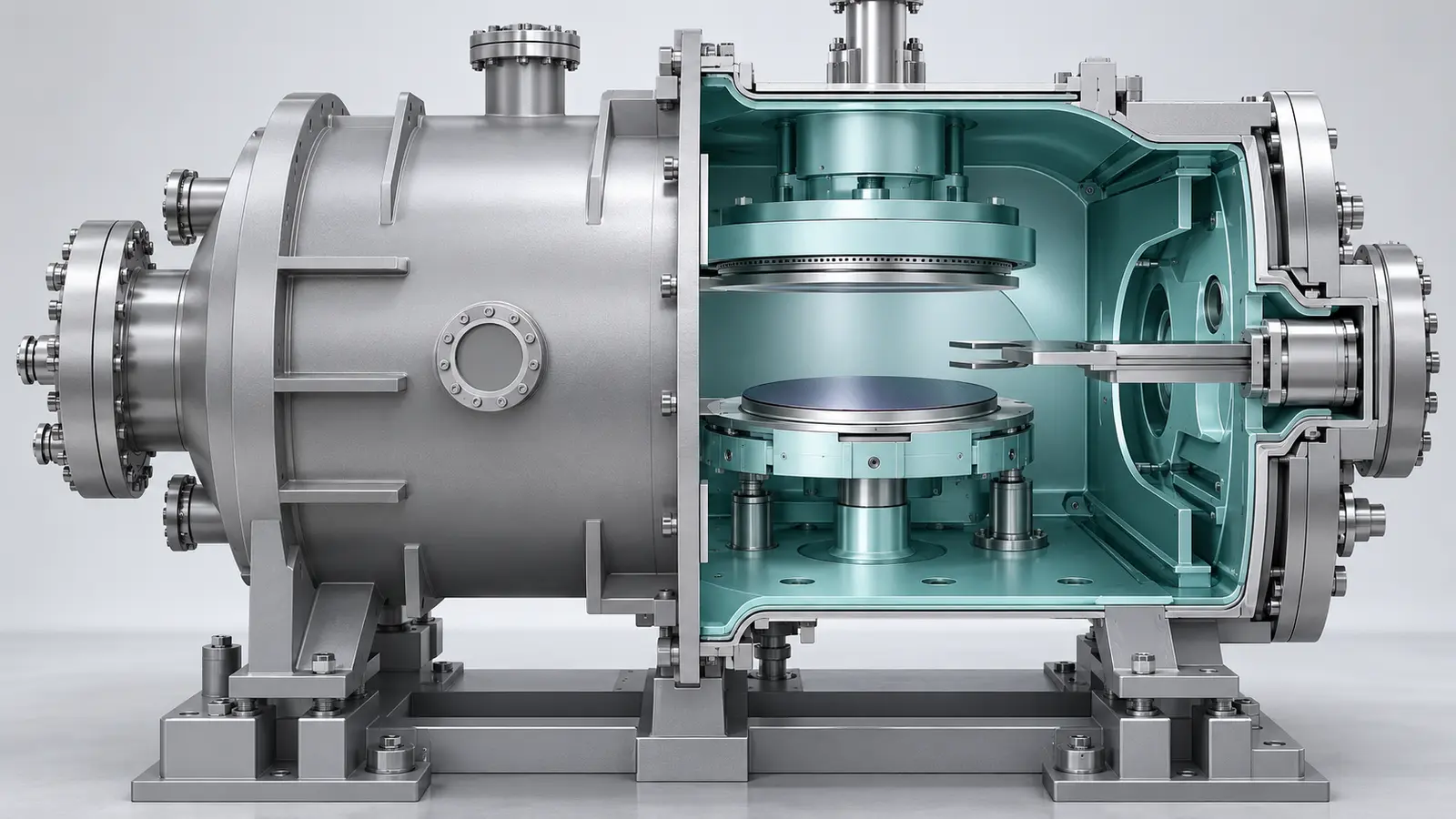
A chamber can be structurally sound and still be unusable for its intended process. External-pressure resistance, seal compression, gas load and wafer alignment are separate requirements. Passing one does not establish the others.
| Design requirement | What belongs in the specification | What it does not prove |
|---|---|---|
| Structural integrity | Load cases, allowable deformation, material condition and engineering review | Cleanliness or vacuum leak tightness |
| Vacuum integrity | Test configuration, allowable leak rate and verification conditions | Acceptable particle generation |
| Process compatibility | Exposed materials, temperatures, chemicals and approved treatments | Dimensional interchangeability |
| Mechanical repeatability | Datums, locating features and assembled alignment | Required pump-down time |
Flat plates and cylindrical shells do not respond to external pressure in the same way. Large openings, thin ligaments between ports and local attachments change the load path. Wall thickness cannot be selected from overall chamber size alone. Use an appropriately qualified mechanical assessment for the actual geometry and service conditions; a generic wall-thickness chart is not a release calculation.
Also define the acceptance state. A face measured while tightly clamped on a machining fixture can meet its drawing tolerance yet move after release. Inspection should reflect the free or assembled state identified by the designer.
Ports are part of the pumping path
A pump’s nameplate speed is not automatically the speed available at the chamber. Restrictions between the pump and the working volume reduce effective pumping speed. Short, accessible connections may therefore help more than simply selecting a larger pump.
Reserve the working envelope
Lay out the wafer sweep, chuck movement, source clearance and service tools before placing gauge and pump ports. A port that is easy to machine may obstruct a robot or place a gauge where its reading poorly represents the region of interest. Pressure distribution and gas flow require process-specific assessment rather than a decorative arrangement of evenly spaced flanges.
Give trapped volumes an escape route
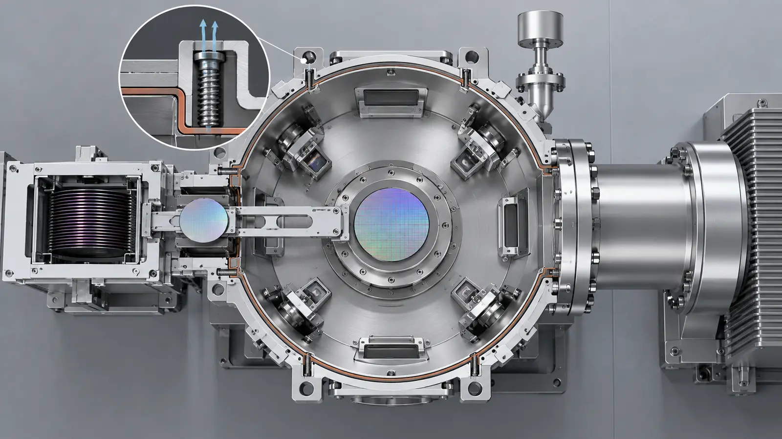
Blind screw holes, overlapping joints and enclosed pockets can release trapped gas slowly. These virtual leaks behave differently from a direct opening to atmosphere. Review each vacuum-side fastener and intersecting passage for a deliberate evacuation path without creating a new path across the pressure boundary.
Keep cleaning access in this layout review. A passage that can be drilled is not necessarily one that can be inspected, rinsed and dried. Specify how passage intersections and burrs will be checked before closing an assembly permanently.
Choose a manufacturing route around the critical interfaces
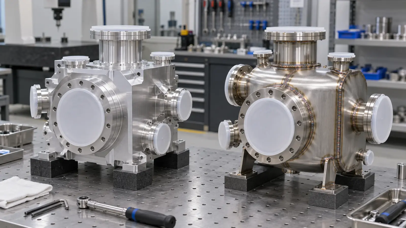
Machining a chamber from solid stock can reduce welded joints and integrate accurate ports, locating faces and seal grooves. It also removes substantial material and can release residual stress. A welded stainless structure may use material more efficiently for a larger envelope, but weld access, distortion and finishing stock need planning before fabrication.
Per CNC-machined chamber components, identify the sealing plane and functional datums first. Features referenced to the wafer-handling interface should not inherit avoidable setup error from an unrelated outer surface.
A practical routing review asks which features are rough-machined, which are completed after joining or other dimensional changes, and which must remain protected throughout handling. Do not prescribe a generic heat treatment: suitability depends on alloy, temper, weld condition and dimensional requirements.
Aluminum and stainless steel remain separate material decisions, not labels for cheap and premium quality. Match the stock condition and joining route to the temperature, chemical exposure and seal interface. Cast or additively manufactured pressure-boundary parts require their own porosity and qualification assessment; they are not direct substitutes for qualified wrought construction.
Make maintenance a design input
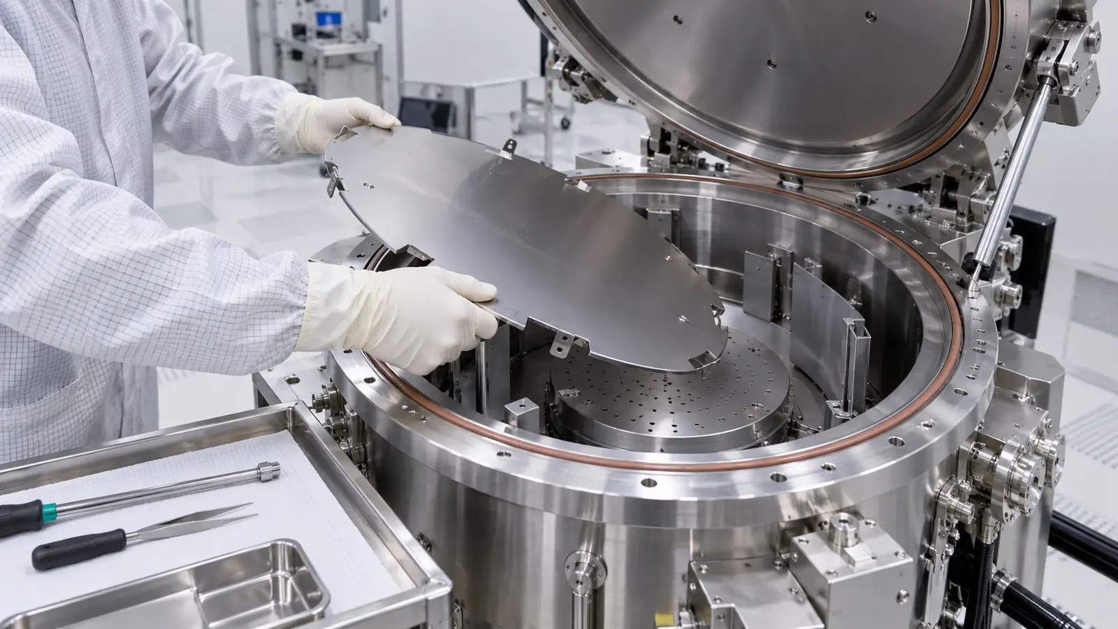
Semiconductor chambers are opened to replace consumables, remove deposits and inspect internal parts. A layout that is serviceable only by touching a seal face or dragging a shield across a wafer-handling surface adds contamination risk at every intervention.
- Provide a supported place for a removed lid or shield, with sealing surfaces protected.
- Allow tools to reach fasteners without crossing fragile process-facing features.
- Separate replaceable wear components from expensive chamber-body features.
- Identify seals that must be renewed, inspected or installed in a controlled orientation.
- Keep lifting and retention hardware outside the clean working volume where practical.
Surface treatments belong in this maintenance discussion. A coating that tolerates the process may respond differently to the cleaning chemistry or repeated mechanical handling. Define masking boundaries, coating thickness allowances and repair criteria before the part reaches finishing.
Verify the risky features before building the complete tool
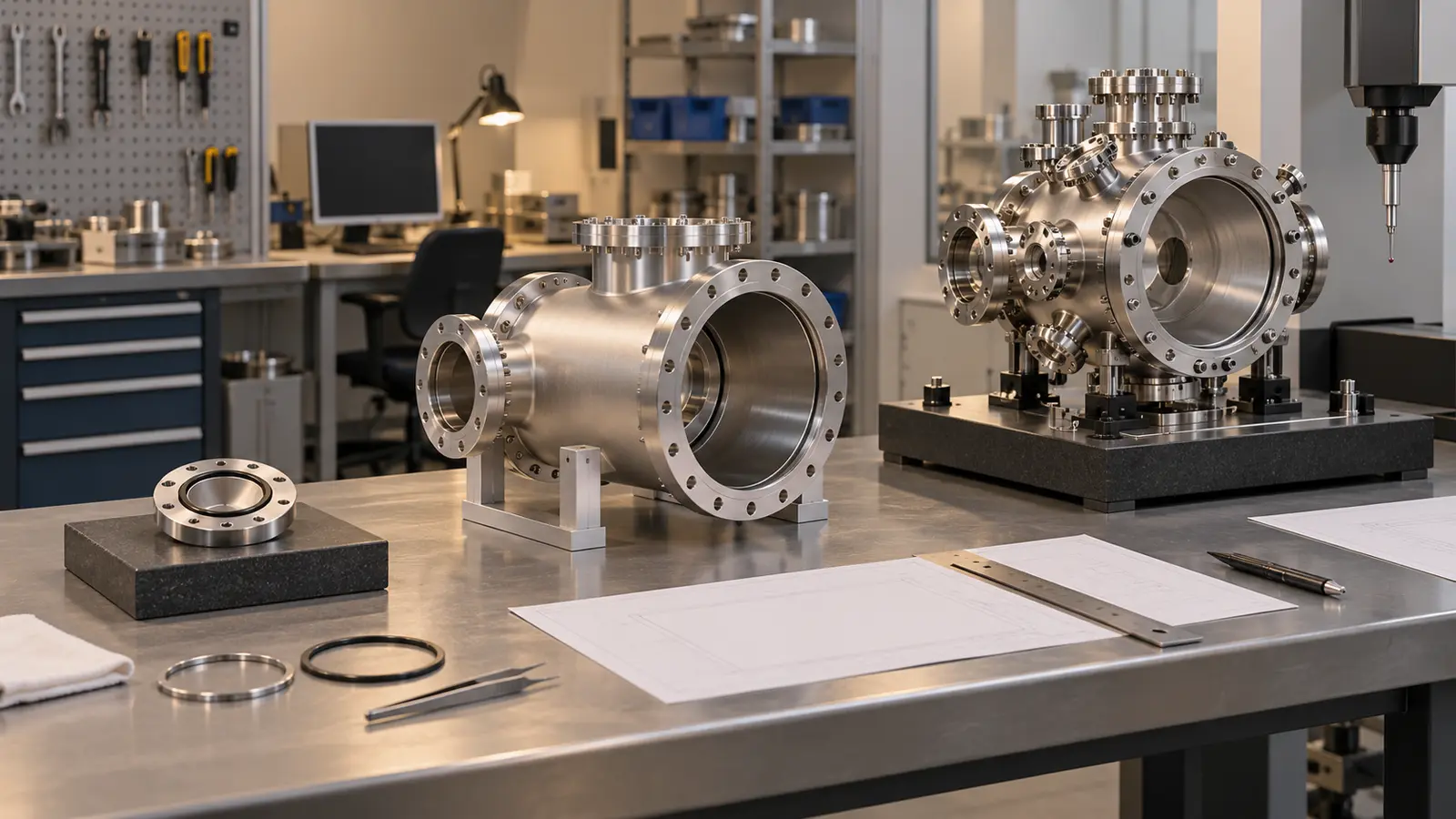
A useful prototype isolates uncertainty. A seal-interface coupon can evaluate machining and assembly behavior. A full-size access mock-up can test lid travel and shield removal. A functional chamber can evaluate pump-down and thermal movement. These are different experiments, and one cannot replace all the others.
Usare structural and functional prototyping to answer a named question, with a measurable acceptance criterion. An unqualified plastic mock-up may demonstrate clearance, but it should not be treated as a safe evacuated pressure boundary.
- Agree the drawing revision, material condition and inspection state.
- Measure critical faces, port relationships and sealing features after the relevant manufacturing operations.
- Inspect accessible internal surfaces and passage intersections before final closure.
- Perform the agreed vacuum integrity and functional checks with documented conditions.
- Protect accepted surfaces and preserve part identification through packaging.
Jucheng Precision’s manufacturing services are relevant to the chamber body, lid, adapters, brackets and other custom mechanical parts. Supply the CAD model together with the interface drawing, exposure map and acceptance requirements so the manufacturing scope can be reviewed. A mechanical component quotation should not be interpreted as qualification of an entire semiconductor process tool.
Questions that should be closed at design review
Does a semiconductor chamber always need ultra-high vacuum?
No. The appropriate pressure environment depends on the chamber’s role and the process. A load lock, transfer module and specialized deposition chamber can have different requirements. State both the operating condition and the base-pressure or pump-down acceptance condition rather than using “UHV” as a quality label.
Can one roughness requirement cover every chamber surface?
Usually that is inefficient. Seal lands, process-facing walls and external mounting surfaces perform different functions. Define their finish and cleanliness requirements separately, including inspection methods and any coating boundaries.
What should accompany a chamber CAD file?
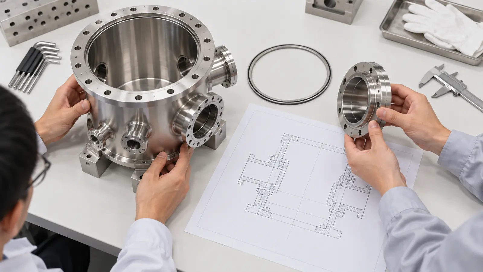
Include material and stock condition, pressure and temperature load cases, port interfaces, critical datums, seal details, surface zones, cleaning requirements and the agreed test scope. These determine whether the model can become a repeatable manufactured part.
Technical context: Applied Materials PVD overview. Load-path, manufacturing and review recommendations above are engineering planning guidance, not a certified vessel design.

