


Sottile è bello finché non diventa un incubo di vibrazioni. Nel vuoto digitale del software CAD, uno spessore di parete di 0,2 mm appare elegante ed efficiente in termini di peso. Tuttavia, nel momento in cui quel progetto incontra il mandrino a 12.000 giri/min di una fresatrice a 5 assi, le leggi della fisica prendono il sopravvento. Il metallo non è più un solido statico; si comporta come una canna vibrante, deviando dall'utensile e assorbendo calore che non può dissipare. Questo è l'ostacolo principale nella moderna linee guida di progettazione per la lavorazione CNC. Raggiungere la leggerezza senza sacrificare la producibilità è il segno distintivo di un ingegnere di livello mondiale.

Presso Jucheng Precision, abbiamo esaminato oltre 10.000 progetti unici, e gli errori di spessore delle pareti rimangono il motivo più frequente di ritardi nei progetti e superamento dei costi. Una parete troppo sottile porta a "vibrazioni"—microscopiche oscillazioni che rovinano le finiture superficiali—e a "ritorno elastico," dove il pezzo si muove fisicamente durante la taglio e finisce fuori tolleranza. Questa Guida allo Spessore delle Pareti CNC è basata su dati grezzi di officina, progettata per aiutarti a spingere i limiti dei tuoi materiali assicurando che i tuoi pezzi possano essere effettivamente realizzati. Che tu stia lavorando con alluminio di grado aerospaziale o plastiche mediche ad alta purezza, comprendere queste soglie è essenziale per trasformare un concetto brillante in una realtà fisica funzionale.
La produzione di successo è l'arte del compromesso tra ambizione strutturale e stabilità meccanica. Non puoi ignorare la pressione dell'utensile, e certamente non puoi ignorare lo stress interno del materiale. Esaminiamo i pilastri tecnici della progettazione delle pareti che assicurano che i tuoi componenti sopravvivano alla macchina e prosperino sul campo.
La Fisica del Fallimento: Perché lo Spessore delle Pareti Conta
Soglie dei Metalli: Navigare dall'Alluminio al Titanio
Sensibilità delle Plastiche: Polimeri Rigidi vs. Flessibili
Coerenza Geometrica: La Regola dell'Uniformità
Approccio Tecnico di JUCHENG: Controllo CAM e Pressione
La Fisica del Fallimento: Perché lo Spessore delle Pareti Conta
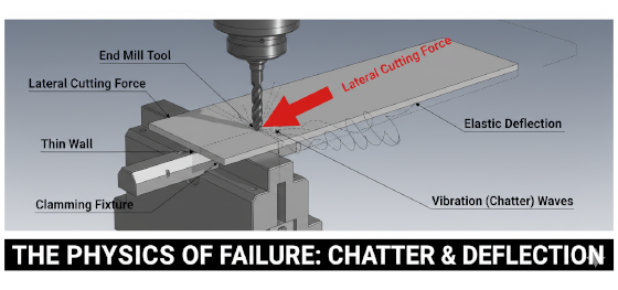
Ogni volta che un utensile CNC impegna un pezzo, esercita una quantità specifica di forza. In un blocco solido, questa forza è facilmente assorbita dalla massa del materiale. Ma man mano che assottigli le pareti, quella massa scompare, lasciando il materiale vulnerabile alla "deflessione." La deflessione è l'atto fisico del materiale che si piega lontano dal tagliente. Immagina di provare a tagliare un foglio di carta sottile tenuto solo a un'estremità—la carta si muove semplicemente con la lama piuttosto che essere tagliata. Questo è esattamente ciò che accade a livello di micron durante linee guida di progettazione per la lavorazione CNC l'implementazione.
Quando una parete deflette, inizia a vibrare ad alte frequenze, portando a un fenomeno noto come "vibrazione." La vibrazione è il nemico della precisione; crea una finitura superficiale a buccia d'arancia e può causare scheggiature o rotture dell'utensile. Ancora peggiore è il problema dello stress residuo. La maggior parte delle materie prime—che siano alluminio estruso o plastica stampata—ha energia interna intrappolata nella loro struttura granulare. Quando rimuoviamo grandi quantità di materiale per creare pareti sottili, stiamo rilasciando quelle "molle molecolari." Senza abbastanza spessore di parete per resistere a queste forze interne, il pezzo si deformerà, si incurverà o si torcerà in una forma non conforme. Questo è il motivo per cui una Guida allo Spessore delle Pareti CNC must account for both the external pressure of the tool and the internal biology of the material. At Jucheng Precision, we look at the "Aspect Ratio"—the relationship between a wall’s height and its thickness. A tall, thin wall is exponentially more difficult to machine than a short, thin one. We advise maintaining a height-to-width ratio of less than 10:1 for best results.
Soglie dei Metalli: Navigare dall'Alluminio al Titanio
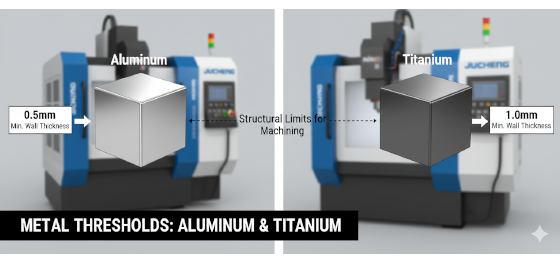
Different metals have different "floors" when it comes to thickness. This is dictated by the material's Young’s Modulus—its inherent stiffness. Aluminum, the most common material in CNC shops, is relatively forgiving. For standard commercial parts, JUCHENG recommends a minimum wall thickness of 0.8mm. In specialized aerospace applications where weight is critical, our master machinists can push this down to 0.5mm, provided the geometry is supported by neighboring ribs or features. However, going below 0.5mm in aluminum significantly increases the scrap rate and machine time, as we must take incredibly light "whisper" cuts to prevent the metal from tearing.
For tougher alloys like Stainless Steel and Titanium, the rules shift upward. Because these materials require much higher cutting forces to shear, they put more stress on the part. For 304 or 316 stainless, a minimum wall of 1.0mm is the safe engineering threshold. Titanium, while possessing an incredible strength-to-weight ratio, is notorious for its low thermal conductivity. A thin titanium wall cannot move heat away from the tool, which often leads to localized overheating and dimensional drift. We recommend a 1.0mm floor for titanium structural components to ensure the heat-affected zone doesn't compromise the material’s properties. By respecting these metal-specific limits, you ensure your design remains structurally sound and economically viable for high-precision CNC machining design guidelines.
Sensibilità delle Plastiche: Polimeri Rigidi vs. Flessibili
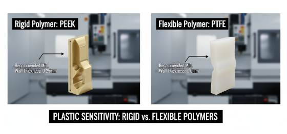
Machining thin walls in plastics is a high-wire act of thermal management. Unlike metals, which can dissipate heat through the workpiece, plastics act as insulators. If a wall is too thin, the heat of the cut will soften the polymer, causing it to "gum up" or melt rather than shear. For rigid engineering plastics like Nylon 66 o Machining PEEK, Jucheng Precision recommends a minimum wall thickness of 1.5mm. These materials have the structural "spine" to stay vertical during a cut, but anything thinner risks significant warping during the cooling phase.
When we move to soft, low-friction polymers like PTFE (Teflon), the Guida allo Spessore delle Pareti CNC must be even more conservative. PTFE is effectively a "solid liquid"; it flows under its own weight and has almost no rigidity. For PTFE components, we suggest a minimum wall of 2.0mm to 2.5mm. If a designer specifies a 1mm wall in PTFE, the material will simply "flutter" in front of the tool like a flag in the wind, making it impossible to hold a tolerance. Furthermore, plastics are highly hygroscopic; thin walls absorb moisture faster than thick ones, which can lead to rapid dimensional expansion. At JUCHENG, we analyze the "thirst" of your polymer choice and adjust our DFM feedback to ensure your thin-walled parts stay in spec even in humid environments.
Coerenza Geometrica: La Regola dell'Uniformità

The secret to a stable part isn't just the thickness—it is the consistency of that thickness. The most common error in linee guida di progettazione per la lavorazione CNC is the transition from a very thick section to a very thin one. This creates a "thermal bottleneck." During machining, the thick section holds onto heat while the thin section cools rapidly. This temperature differential creates internal stress that pulls on the part, leading to a permanent bow or twist. We call this the "Asymmetric Pull."
JUCHENG engineers advocate for the "Uniformity Rule": keep your walls as consistent as possible across the entire part. If you need a thin feature, try to pocket out the surrounding heavy areas to balance the material mass. This homogenizes the stress distribution. We also advise against sharp transitions at the base of thin walls. A sharp 90-degree corner where a thin wall meets a heavy floor is a prime location for stress cracks to begin. By adding a small radius (fillet) at the base, you distribute the cutting forces and create a much more durable part. A well-designed 1.0mm wall with generous fillets will often outperform a 1.5mm wall with sharp corners in both the machine shop and the field.
Approccio Tecnico di JUCHENG: Controllo CAM e Pressione

At the end of the day, achieving the impossible in wall thickness is a matter of software and strategy. Jucheng Precision doesn't just use standard milling cycles for thin-walled parts. Our CAM department utilizes "Trochoidal Milling" and high-speed "Peeling" toolpaths. These strategies keep the tool engagement at a constant, low percentage—typically 10% to 15% of the cutter diameter. By taking thousands of tiny, rapid bites rather than one big one, we keep the cutting pressure so low that the wall doesn't even realize it's being machined.
We also utilize specialized workholding like "Cryogenic Fixturing" or "Wax Clamping" for extremely delicate foils and thin-walled manifolds. By supporting the material from the inside out or freezing it into a solid block of ice during the cut, we provide the temporary rigidity needed to achieve thicknesses that were once thought impossible. Our quality control team uses non-contact laser scanning to verify wall thickness without the risk of deforming the part with physical probes. When you receive a component from JUCHENG, you are getting the benefit of optimized physics and advanced CAM engineering. Whether you are building an ultra-lightweight drone chassis or a complex satellite housing, our Guida allo Spessore delle Pareti CNC ensures your design is flight-ready and cost-effective. Contact Jucheng Precision today for a free DFM review and see how our technical rigor can clarify your next thin-walled challenge.

