


A throttle plate that moves freely on the bench can bind after the housing is bolted to its mating assembly. Automotive throttle body machining must account for the bore, shaft supports, plate relationship and mounting condition together. Checking the bore diameter alone can miss the feature relationship that causes the problem.
This article addresses manufacturing a drawing-defined throttle housing and its mechanical interfaces for an OEM development or component supply project. Airflow targets, control electronics, emissions requirements and vehicle calibration remain separate engineering responsibilities. The useful manufacturing question is narrower: what changes between an unassembled machined housing and the condition in which its geometry must work?
Locate the stage where movement changes
Begin with the build sequence. Record whether resistance appears when the shaft is installed, when the plate is attached, after finishing, or only after the housing is mounted. These are different observations, and they point to different checks. Changing a machining dimension before locating the change can conceal one problem while creating another.
For a development assembly, use the specified components and assembly procedure. An unidentified shaft or a convenient substitute plate may help explore a concept, but it cannot establish acceptance of the intended combination. Record the revisions and actual part identities so that a later comparison is meaningful.
Keep the inspection result separate from the diagnosis. A housing may have a measured deviation, but that deviation is not automatically the cause of the observed resistance. Compare the geometry, assembly condition and evidence before deciding what to change. If the design requires a functional movement check, agree on its setup and acceptance method with the design owner.
This component sits within the broader CNC automotive machining scope. Its value as a separate manufacturing topic comes from the interaction of the moving plate, transverse shaft and housing bore, rather than from a general explanation of engine air intake.
Inspect the shaft supports in the bore reference
The shaft support features establish the motion of the plate relative to the passage. Their alignment, location and installed condition must follow the product definition. Measuring each support hole separately can establish local size while leaving their relationship unresolved. Decide how both supports are evaluated in a common reference system.
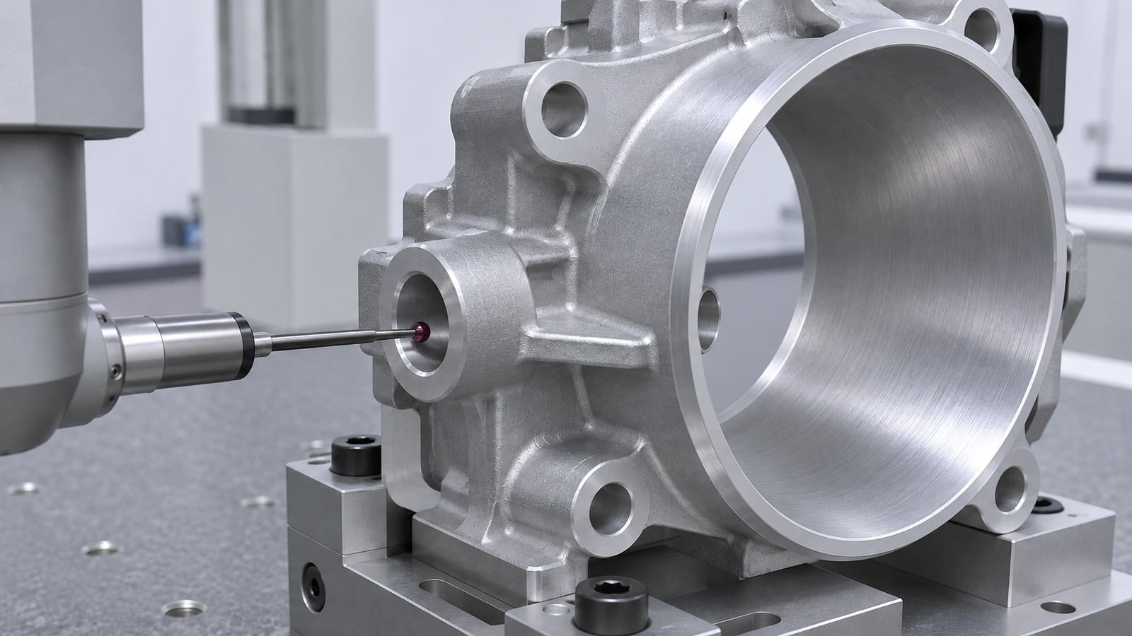
The passage itself may have a specified straight or shaped profile. Do not simplify it to a nominal cylinder because a standard tool or gauge makes that easier. Identify which surfaces control the plate relationship and which surfaces are primarily flow transitions. Their manufacturing and inspection requirements need not be identical.
A practical drawing review asks where the shaft axis is located relative to the bore and mounting features, whether any intentional offset exists, and which configuration controls final inspection. A supplier should request clarification where these relationships are ambiguous. Inferring them from an attractive CAD rendering is not enough.
Plate position and attachment also matter. Machining the housing accurately cannot correct an incorrectly specified plate, a mismatched shaft feature or an uncontrolled assembly step. Review the mechanical interfaces together, while keeping responsibility for component manufacture and assembly validation explicit.
Use the mounting face as part of the investigation
A free housing and a mounted housing may not have the same shape. Local wall thickness, contact conditions, fastener loading and the stiffness of the mating assembly can influence the installed geometry. This does not mean every housing will distort significantly; it means the acceptance condition must be defined rather than assumed.
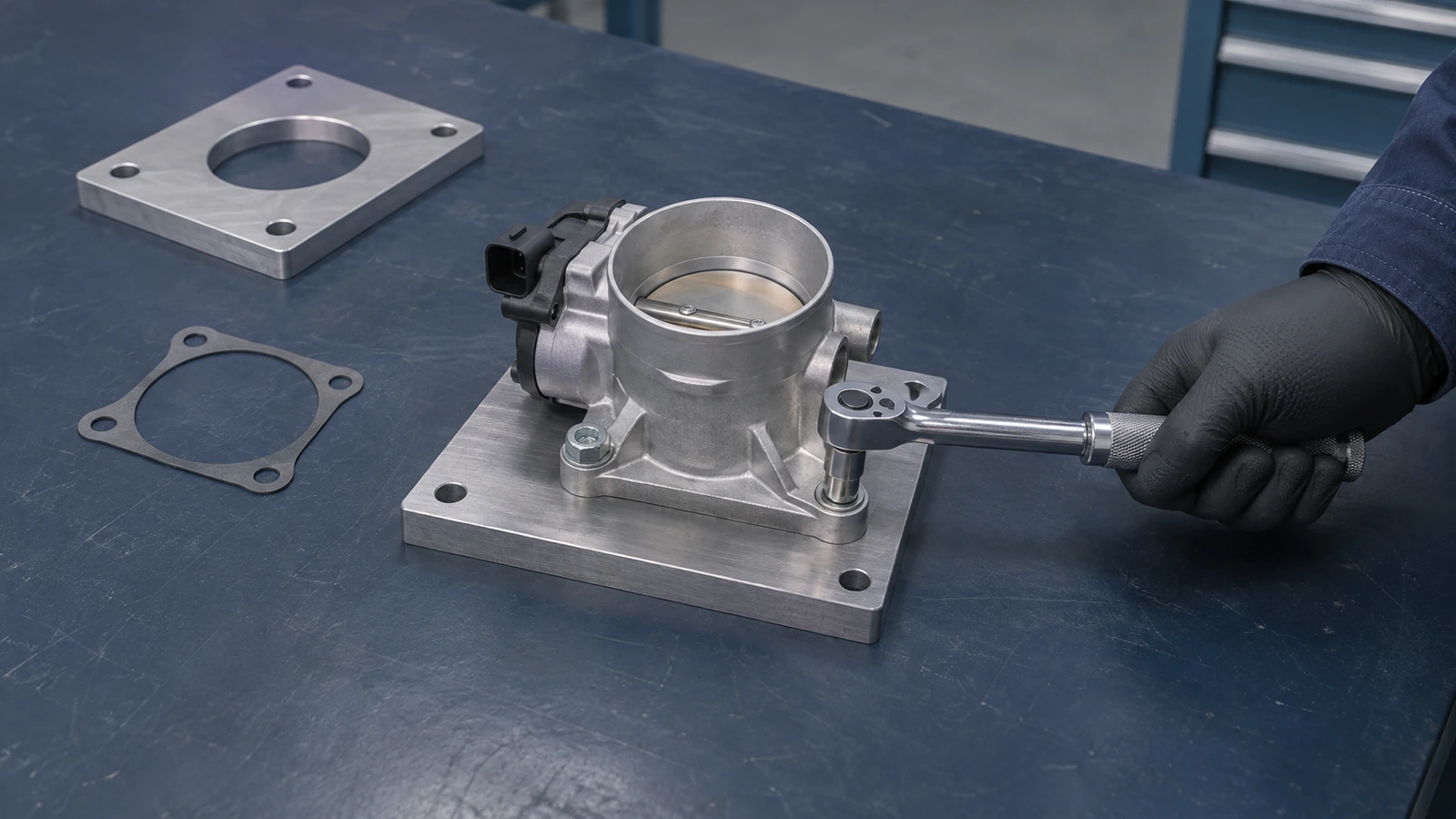
Inspect the mounting face in its specified condition. Identify the sealing arrangement and whether a gasket or other interface is part of the functional evaluation. A flat face alone does not establish the location of the shaft axis or guarantee that the passage remains correctly aligned when assembled.
The adjacent intake manifold manufacturing topic covers the manifold and its interfaces. Here the focus remains the throttle housing: what it presents to that interface and what mounting does to its own geometry. This distinction helps prevent two articles from repeating the same discussion of airflow passages.
For a prototype investigation, agree on a representative fixture or mating component and a documented assembly condition. Compare free and mounted measurements only when the measurement methods are suitable for that comparison. Do not use extra clamping to force a nonconforming part into an apparently acceptable shape.
Choose billet or casting around the development question
A machined billet housing can be useful when the team needs to change passage geometry or mounting features before committing to tooling. A cast blank can become more relevant when the casting route, local wall behavior or near-production geometry is itself being evaluated. The correct choice depends on what the sample must demonstrate.
| Development question | Route to consider | What remains unproven |
|---|---|---|
| Will the mechanical interfaces fit? | Drawing-based billet prototype | Behavior of the intended production casting |
| Can the cast geometry be finished consistently? | Specified casting with planned machining stock | Long-term process capability without supporting production evidence |
| Does the finished assembly move as required? | Representative material, finish and assembly condition | Vehicle-level performance beyond the agreed component test |
Material condition belongs in this decision. Review la lavorazione delle leghe di alluminio against the actual grade and product form required. A readily available wrought alloy does not automatically represent a casting alloy simply because both are aluminum. State any permitted prototype substitution and its limitations.
The distinction is visible in industry practice: AT Power describes CNC-machined billet throttle bodies for its own product architecture. That is evidence of a possible manufacturing route, not a reason to copy its geometry or claim the same performance for another design.
Leave finishing allowance where it changes fit
Finishing can change the accepted dimensions or surface condition of a component. The drawing should identify whether a dimension applies before or after treatment, and which areas require masking or protection. This matters particularly around shaft supports, seal interfaces and surfaces close to the moving plate.
A route that finishes the bare housing to its final limit and only then considers treatment may leave no controlled allowance. Conversely, adding an arbitrary allowance everywhere can produce the wrong fit. Agree on the actual treatment specification and dimensional interpretation before programming the finishing cuts.
Burr removal needs its own access plan. Cross-holes, shaft openings and passage intersections can leave edges that are difficult to reach after assembly. Define the required edge condition and how it will be inspected. Avoid broad polishing instructions that can change a functional contour while making it look visually cleaner.
Cleaning completes the manufacturing handoff. Specify the required cleanliness evidence for the order and protect the finished component during handling and packing. A photograph of a clean-looking bore does not establish the condition of every hidden intersection.
Close the review with a controlled sample
Before ordering, provide the model, drawing revision, material and condition, finish specification, mating interface information and the purpose of the prototype. Identify which assembly or functional checks the supplier is expected to perform. A machining-only quotation should not silently become a complete throttle-system validation commitment.
A focused sample review should compare the same characteristics at the same manufacturing stages: passage geometry, shaft-support relationships, mounting-face requirements and the specified finished condition. When the sample changes, retain the previous revision and the reason for the change. This lets the engineering team distinguish an improvement from a change in measurement or assembly setup.
Jucheng Precision can review a produzione di prototipi request around these interfaces and the supplied part definition. Ask for a clear statement of the proposed blank, machining sequence, finishing scope and inspection deliverables. That discussion provides a practical basis for comparing suppliers and for deciding what the next sample must prove.
If binding remains, return to the documented stage where it first appeared. The next action should follow the evidence: a geometry correction, an assembly clarification, a finish allowance change or further engineering evaluation. Enlarging the bore without identifying the cause is an unreliable substitute for that investigation.

