


Choosing between molding, casting, and machining for semiconductor equipment components is a decision about volume, geometry, material, tooling, and risk. No single process wins in every situation. The best route changes as a part moves from an engineering sample to a repeat production component.
Start with the decision variables
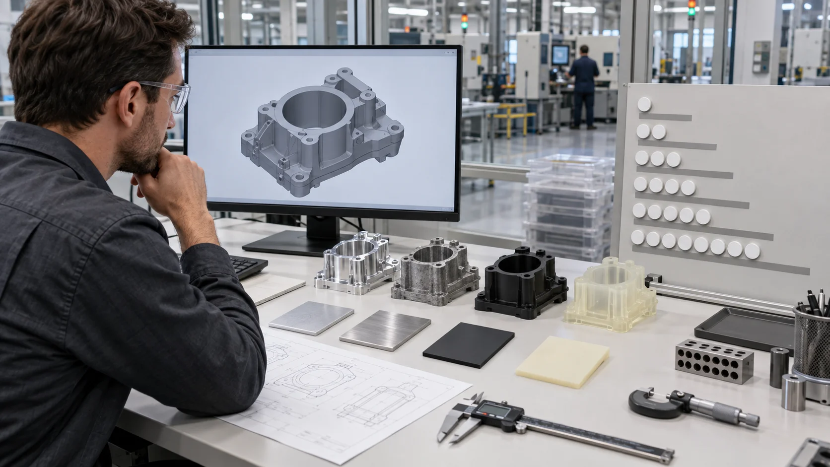
- How many parts are needed now and later?
- Does the geometry require tight machined interfaces?
- What material and surface behavior are required?
- Can the project support tooling cost and lead time?
- Which features must be inspected or modified frequently?
Answering these questions first keeps the process discussion connected to the equipment program and to semiconductor equipment parts manufacturing.
The routes solve different problems
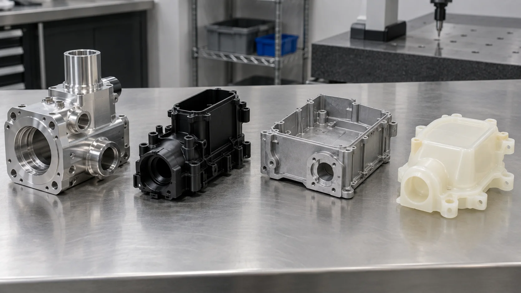
| Route | Best fit | Trade-off |
|---|---|---|
| La lavorazione CNC | Accurate metal or plastic components, low to medium quantities | Higher cycle cost for repeated complex volume |
| Stampaggio a iniezione | Repeated polymer geometry and stable production demand | Tooling investment and shrinkage control |
| Die casting | Repeated metal housings or structural forms | Tooling, draft, and post-machining requirements |
| La colata sottovuoto | Small batches of polymer-like parts and appearance or fit builds | Mold life and material limitations |
Tooling changes the cost curve
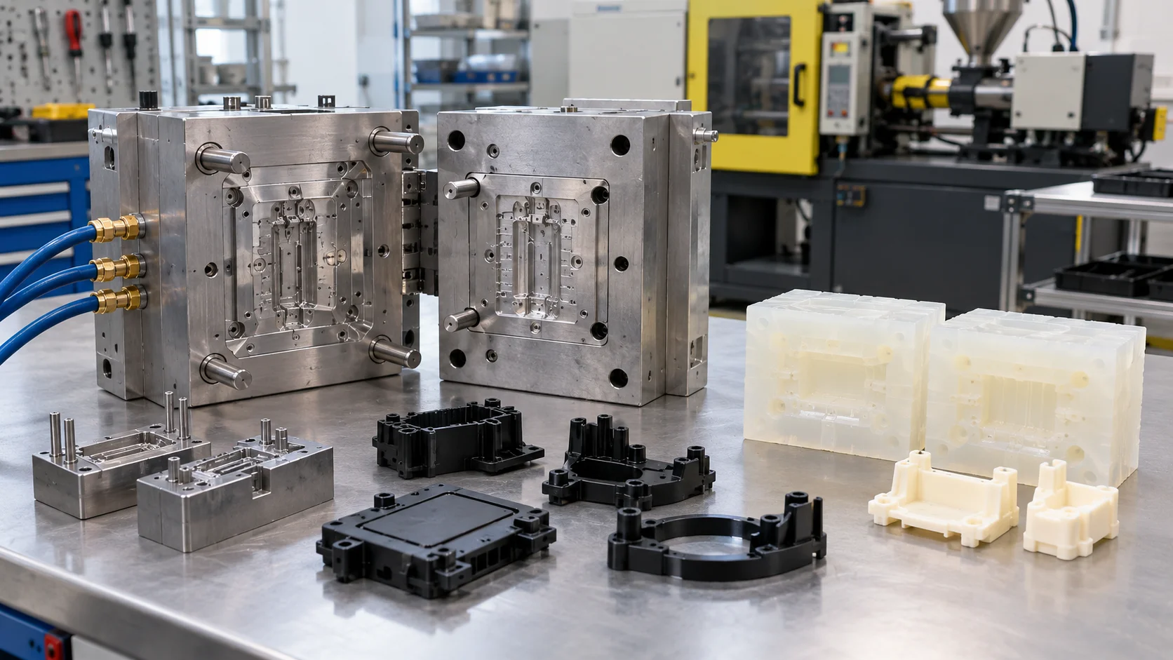
Tooling is not only a price line. It affects design freedom, change cost, launch timing, and the number of parts needed to recover the investment. A small equipment program may benefit from machining or a silicone mold making route while the geometry is still changing.
When demand becomes stable, compare the total cost of the current route with the cost of tooling, qualification, maintenance, and future changes. The changeover should be based on evidence rather than an assumed volume threshold.
Surface and interface risk varies by route
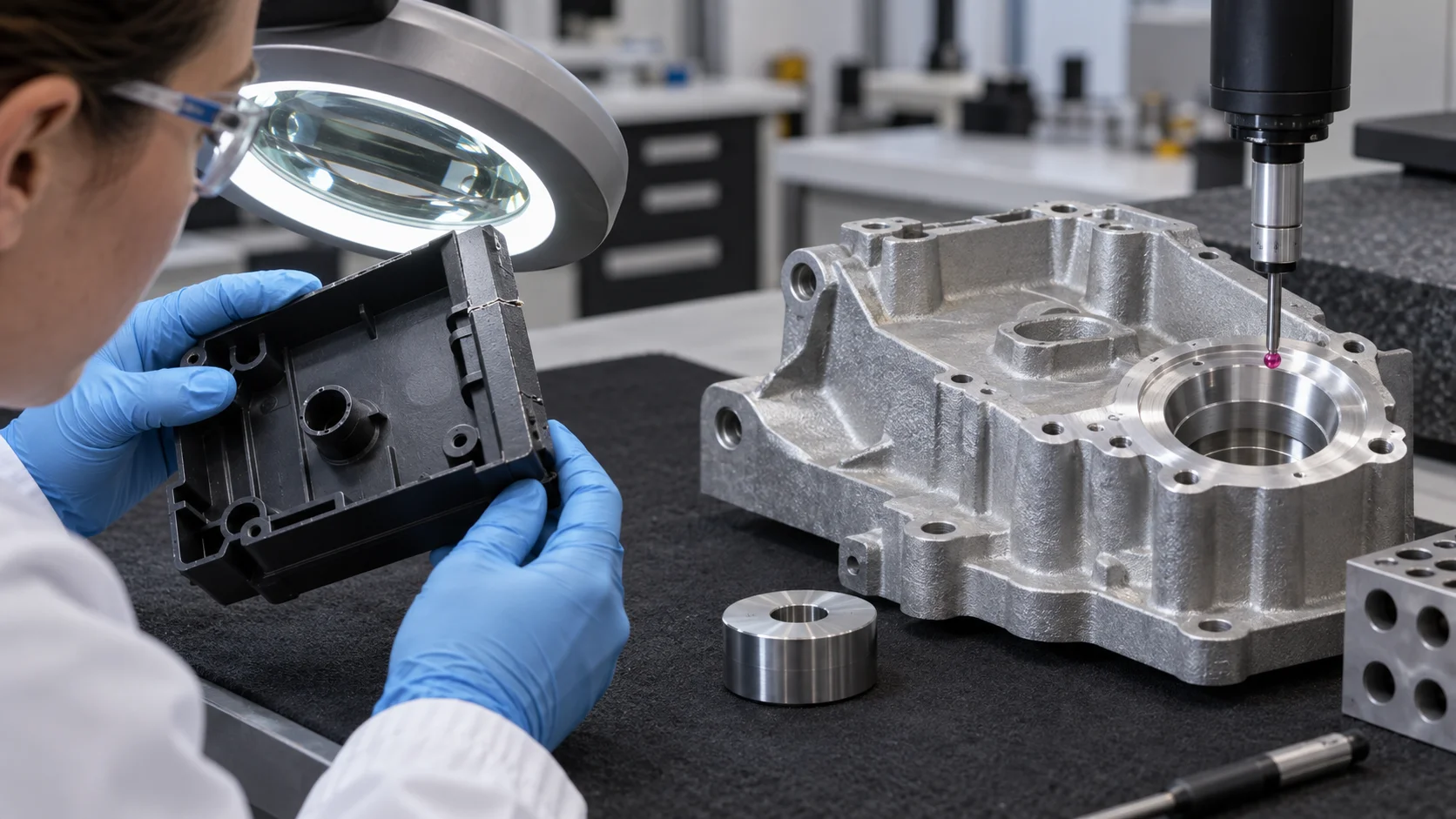
Molded and cast parts may require draft, uniform walls, gates, runners, parting lines, or post-machined interfaces. These features should be reviewed against assembly and cleaning requirements. If a metal housing needs accurate mounting faces, consider a die casting route with defined secondary machining and inspection.
For polymer components, define shrinkage, texture, flash limits, and any finish or cleaning requirement. A process that produces the right shape but the wrong surface can still fail in equipment assembly.
Design the first build for the next one
The first build should reveal what must change before tooling or repeat production. Mark critical dimensions, inspect interfaces, record assembly feedback, and distinguish temporary geometry from frozen geometry. This makes the eventual transition more predictable.
If the part still needs frequent design changes, retain a flexible route. If the design is stable and demand is visible, quantify the tooling case and confirm the supplier can support maintenance and future revisions.
Route selection checklist
- Define the quantity and build stage.
- Identify the geometry that drives tooling or setup cost.
- Separate interface tolerances from general appearance.
- Confirm material, finish, and cleanliness expectations.
- Plan how the first build will be inspected and learned from.
Process Selection Questions
Is machining always better for low volume?
Often, but not automatically. Geometry, material, finish, tolerance, and change frequency may make vacuum casting, rapid tooling, or another route more useful.
When does molding become attractive?
It becomes more attractive when polymer demand is repeated, geometry is stable, and the tooling investment can be justified by total program cost.
Select the Route, Then Validate It
Molding, casting, and machining should be compared as complete production routes. Volume, design maturity, material, tooling, surface, and inspection together determine the best choice for a semiconductor equipment component.

