


First establish how the seal is loaded
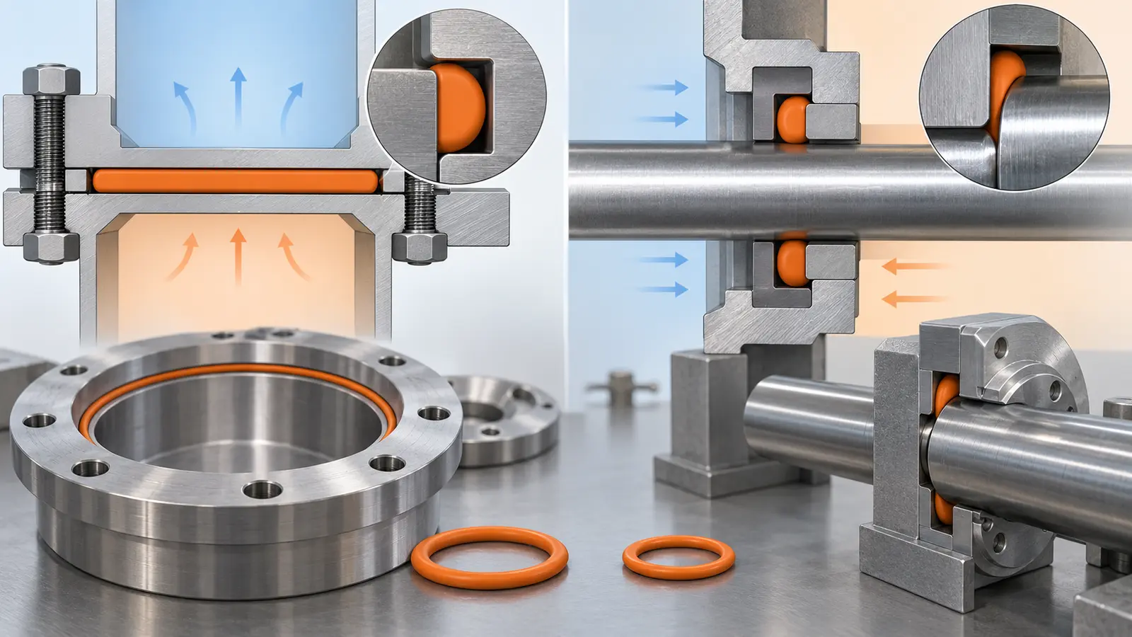
An O-ring gland is the space that contains and supports the seal. A face seal compresses the cross-section between opposing faces; a radial seal compresses it between cylindrical surfaces. Their dimension chains are different. This article concentrates on static face seals in machined semiconductor chamber lids and access plates.
Draw the pressure boundary on the section view. In an evacuated chamber, atmospheric pressure acts from the outside. That pressure direction affects where the ring tends to move and which gland wall supports it. A groove copied from an internally pressurized fluid fitting is not automatically correct for vacuum service.
Distinguish the initial assembly condition from operation. Before evacuation, the joint must already have an adequate sealing arrangement. Vacuum force should not be used to compensate for a warped lid, missing closure hardware or a groove that gives almost no initial compression.
On a semiconductor load lock, repeated access also matters. A ring that seals once but twists, drops out or sheds particles during each opening has not solved the equipment problem.
Squeeze and gland fill answer different questions
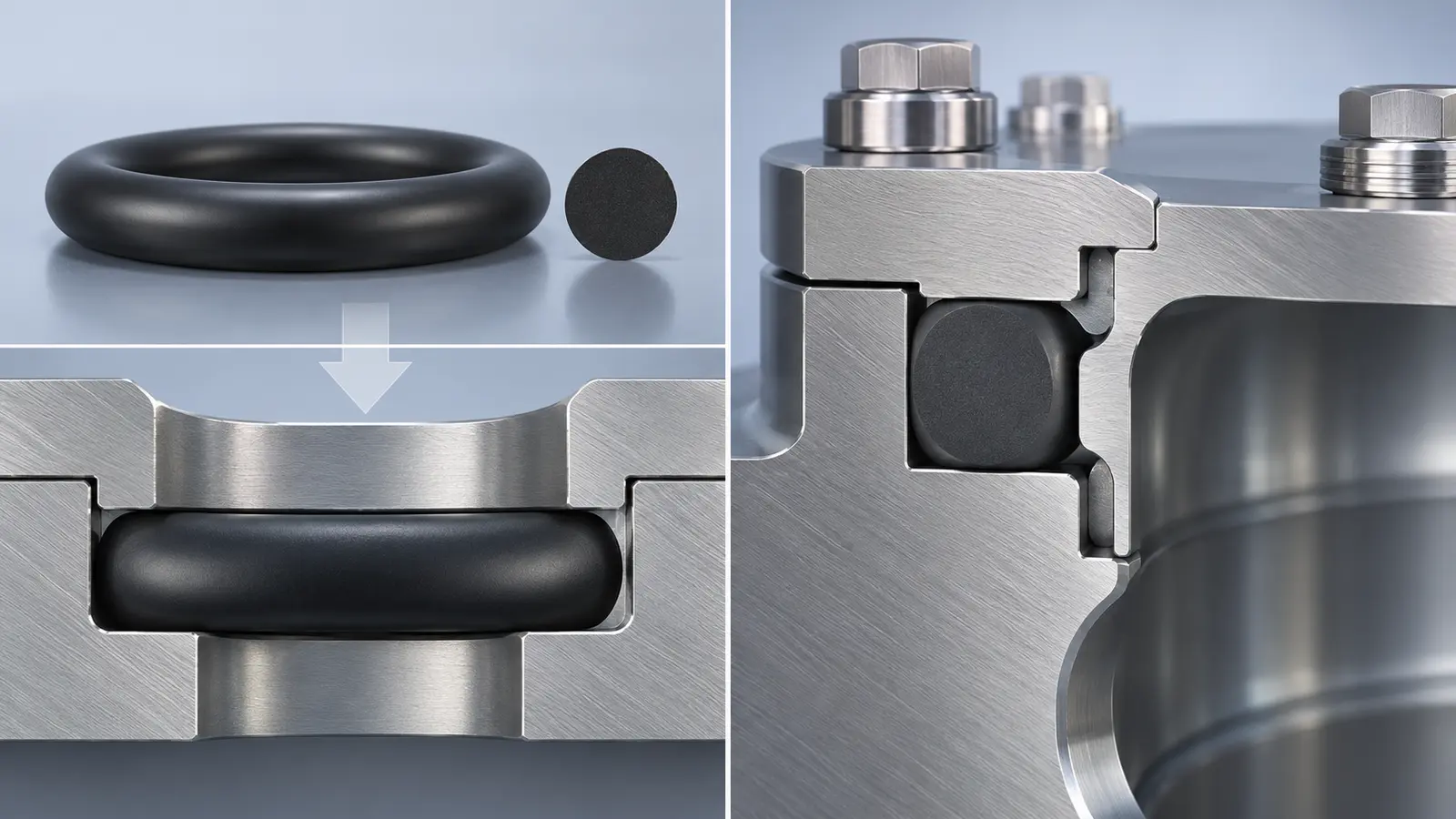
Squeeze is the reduction in O-ring cross-section caused by assembly. Gland fill is the proportion of the available gland volume occupied by the elastomer. A design can have plausible squeeze and still leave insufficient room for the seal to expand.
| Quantity | Simplified relationship | Boundary of the calculation |
|---|---|---|
| Face-seal squeeze | (d − h) / d × 100% | d is effective cross-section; h is assembled gland height |
| Cross-sectional gland fill | [πd²/4] / [b × h] × 100% | Approximation for a rectangular section; radii, stretch and actual volume matter |
| Minimum squeeze | Smallest effective ring with greatest assembled height | Include tolerances and face separation |
| Maximum squeeze | Largest effective ring with smallest assembled height | Also evaluate thermal and chemical dimensional changes |
Here, b is groove width. These expressions help explain the geometry; they are not a substitute for a seal manufacturer’s gland recommendations. A real rectangular chamber seal also has corner geometry and an installed perimeter that the simple section calculation does not represent.
Il Parker O-Ring Handbook provides application-specific gland guidance. Select the applicable seal arrangement and compound before taking dimensions from a table. Do not transplant one compression percentage across face, radial, dynamic and retained seals.
A nominally correct groove can fail at the tolerance limits
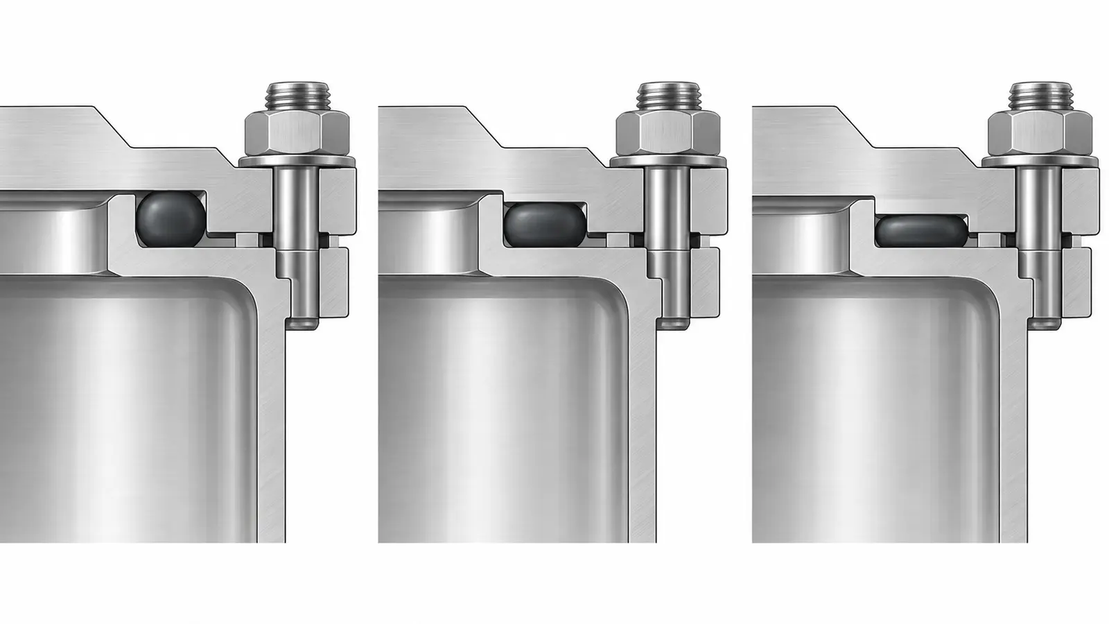
Consider an illustrative static face seal with a nominal 3.00 mm cross-section and an assembled gland height of 2.40 mm. The simplified nominal squeeze is 20%. Those numbers are chosen only to demonstrate a calculation; they are not recommended groove dimensions.
Now assume the effective cross-section could be 2.92–3.08 mm and the assembled gland height could be 2.35–2.45 mm. The lowest calculated squeeze becomes (2.92 − 2.45) / 2.92, or about 16.1%. The highest becomes (3.08 − 2.35) / 3.08, or about 23.7%. Whether either value is acceptable depends on the selected seal and service.
The overlooked dimension is the assembled height
Groove depth alone does not always equal h. Lid flatness, joint separation, coating on either face, local deformation and the position of any hard stop can change the available space. If a seal land opens locally during thermal cycling, the compression around the perimeter is no longer uniform.
Ecco perché precision machining for semiconductor parts must control relationships between features, not just isolated dimensions. The groove bottom, sealing face and locating surfaces need a coherent datum and inspection strategy.
Check the limiting states separately: cold assembly, stabilized operation and the maintenance or cleaning condition. Elastomer thermal expansion and chemical swelling should be evaluated using compound-specific information, not a generic rubber coefficient.
Machining details that change seal behavior
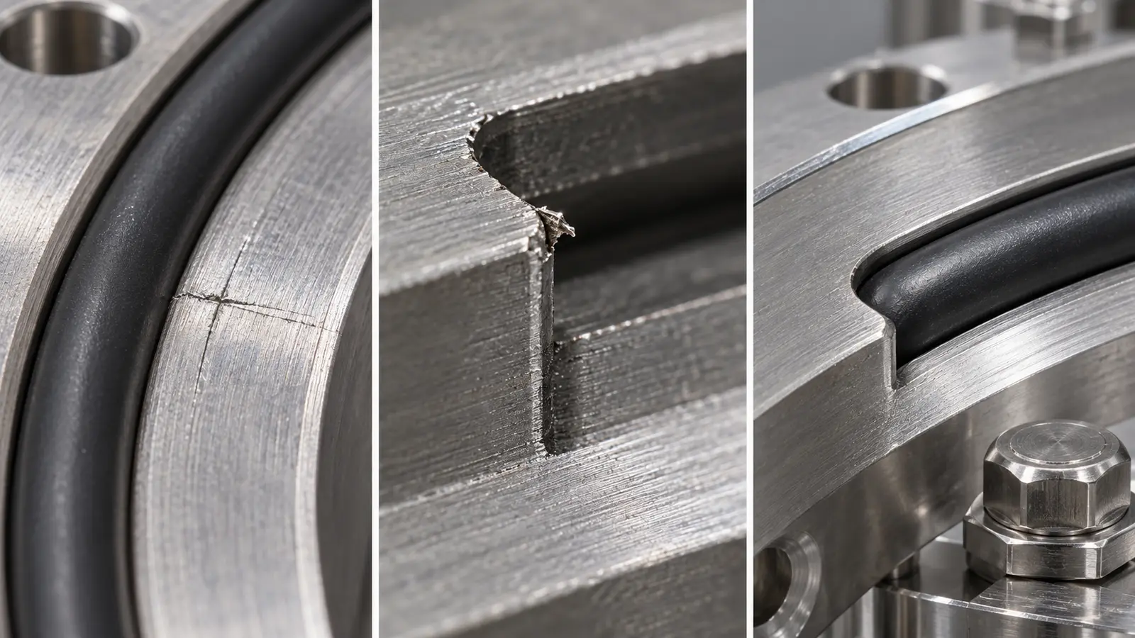
Tool marks must not create a continuous escape path
A numerical roughness result can overlook a scratch that crosses a sealing land. Specify local defect acceptance in addition to the appropriate texture requirement. The machining direction, burr condition and measurement locations should be considered with the seal supplier’s guidance.
Edges need definition, not a blanket deburr note
A sharp groove entrance can cut a ring during installation. Excessive edge rounding can remove the intended supporting geometry or change the gland area. Put important radii and edge breaks on the drawing instead of leaving the result to an unspecified hand-finishing operation.
Retained grooves require an installation strategy
Dovetail or other retained profiles may help keep an O-ring in an overhead lid. They also complicate machining, dimensional inspection and cleaning. The retention feature should not require damaging the ring during insertion or create pockets that cannot be adequately cleaned.
Per custom machined seal grooves, review cutter access at corners, tool reach, groove-width inspection and the sequence of final finishing. A small change in corner radius may improve manufacturability, but it needs approval against the intended ring path.
Choose the compound for the exposure, not the color
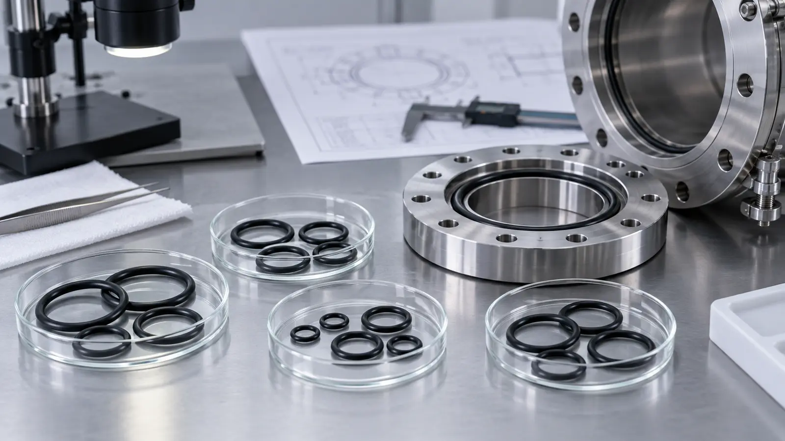
Two black O-rings can have very different chemical resistance, permeability, extractables and compression-set behavior. Material family is a starting point; the specific compound and its documented performance are the relevant engineering inputs.
FKM and FFKM compounds may be considered for some semiconductor applications, but neither is universally suitable for all plasma, cleaning or thermal conditions. EPDM or other families may fit particular environments and fail in others. Specify the required exposure compatibility and consult the seal supplier rather than ranking families as good, better and best.
Also distinguish a physical leak around the seal from gas permeation through it. Changing groove dimensions cannot necessarily overcome the gas-load limit imposed by the compound and exposed seal area. If elastomer-related performance is insufficient, a different sealing architecture may be needed.
Jucheng Precision’s relevant component scope is the machined gland, lid, flange and mating interface. The selected sealing compound and acceptance conditions should be provided or approved by the equipment owner; machining the metal correctly does not independently qualify the purchased elastomer.
Trace the symptom back to the interface
| Observed symptom | Possible mechanism | Useful next check |
|---|---|---|
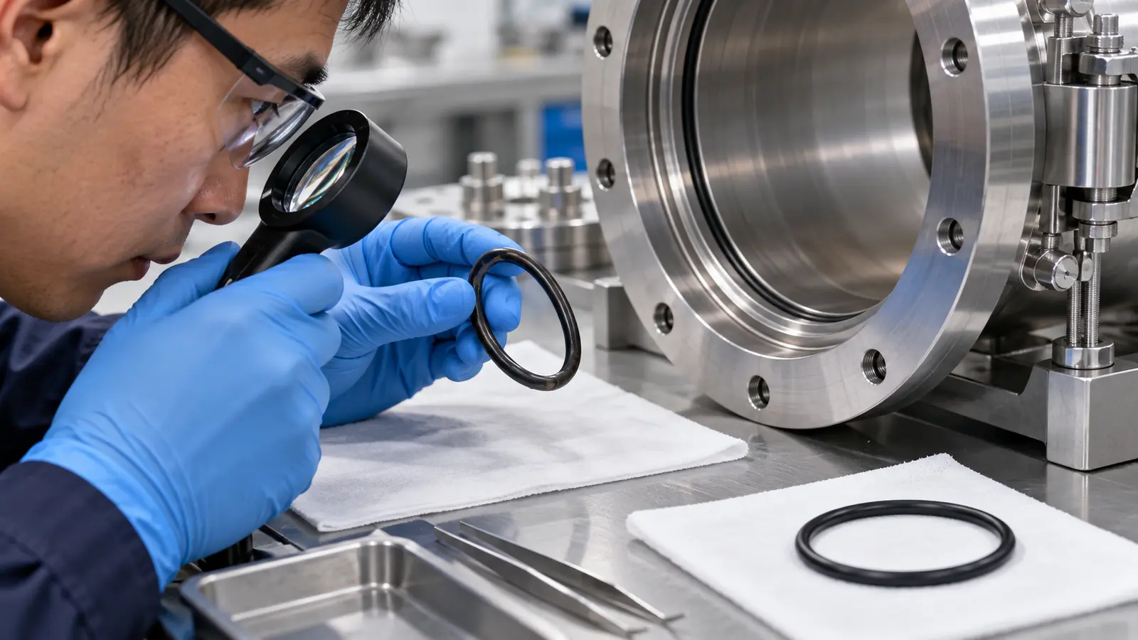
| Leak appears after opening | Ring damage, twist, particles or inconsistent seating | Inspect the removed ring and full sealing perimeter |
| Leak changes with lid position | Uneven closure, face movement or alignment error | Review assembled geometry and support conditions |
| Room-temperature pass, hot-condition failure | Differential expansion or compound incompatibility | Review hot gland height and approved thermal limits |
| Good fit but persistent gas load | Permeation, contamination or trapped volume | Separate sealing geometry from material and cleanliness effects |
These are diagnostic possibilities, not conclusions from symptoms alone. Change one controlled variable at a time and record the test configuration. Additional lubricant, torque or sealant can mask a problem while creating contamination or maintenance consequences.
Include the assembled test definition in the component procurement package: approved seal, installation condition, test medium, allowable result and retest requirements. A groove dimension report and a vacuum leak test answer different acceptance questions.
Can an O-ring be reused after a leak test?
Only when the approved maintenance or test procedure permits reuse and inspection confirms acceptable condition. A ring that has been damaged, contaminated or permanently deformed should not be accepted merely because it still fits.
Does a smoother groove always give a better seal?
No. Geometry, local defects, compound, cleanliness and assembly all matter. Use an application-appropriate finish rather than specifying a mirror surface as a universal cure.

