


What does consumer electronics enclosure manufacturing involve?
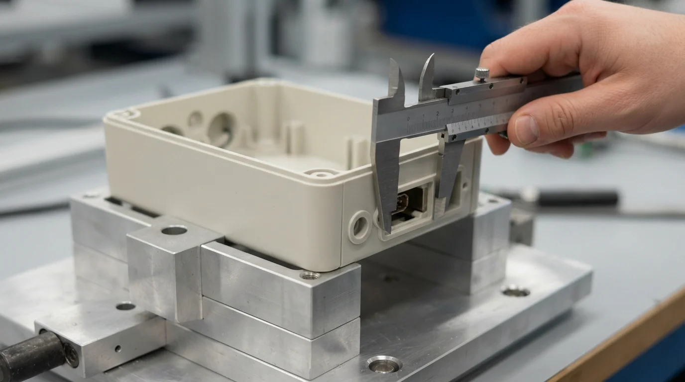
Consumer electronics enclosure manufacturing is the process of turning an electronics housing design into a functional, inspectable, and repeatable part. The enclosure must protect the internal electronics, hold the PCB and interfaces in position, support assembly, and present the intended appearance to the user. It is both a mechanical packaging problem and a manufacturing-process decision.
A housing can look correct in a rendering and still fail during assembly. Common causes include connector cutouts that do not align with the board, bosses that interfere with components, insufficient clearance around cables, unsupported covers, unrealistic sealing features, or cosmetic surfaces that cannot be reproduced consistently. Good enclosure manufacturing starts by checking these risks while the design can still be changed economically.
| Requisito | Questions to answer |
|---|---|
| Internal packaging | Where are the PCB, battery, display, antenna, buttons, cables, and fasteners located? |
| Protection | Must the housing resist impact, dust, moisture, heat, chemicals, or repeated handling? |
| Aspetto | Is the product expected to have a molded texture, brushed metal, painted surface, or transparent window? |
| Production volume | Is the need one prototype, a pilot batch, low-volume production, or a repeatable high-volume part? |
| Assemblaggio | How will the housing, gaskets, screens, and electronic components be joined and serviced? |
The enclosure should be developed together with the electronics rather than added after the board layout is finished. Independent design decisions often create a late conflict between the desired exterior form and the space required by the internal hardware. A manufacturability review can identify those conflicts before tooling or a larger production order is committed.
Which manufacturing process fits the enclosure?
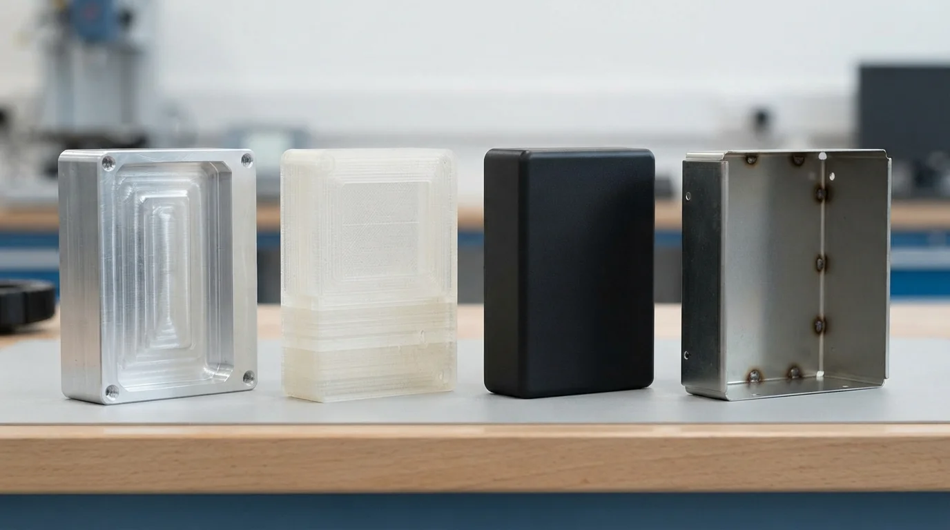
No single enclosure manufacturing process is best for every consumer product. The right choice depends on the stage of development, part geometry, material, finish, quantity, and tolerance risk. A useful comparison is not “Which process is cheapest?” but “Which process creates the required part with the lowest total development risk?”
| Processo | Good fit | Main advantage | Important limitation |
|---|---|---|---|
| stampa 3D | Early form, fit, and ergonomic prototypes | Fast design iteration without production tooling | Surface and material behavior may differ from the production part |
| La lavorazione CNC | Precision prototypes, metal housings, bezels, and low-volume parts | Direct production from solid stock with strong dimensional control | Deep internal features, thin walls, and undercuts can increase cost |
| La fabbricazione della lamiera | Durable metal enclosures, chassis, covers, and pilot batches | Efficient for folded metal structures and design changes | Bend radii, reliefs, fasteners, and joining constrain the form |
| Stampaggio a iniezione | Repeatable plastic housings when quantity and appearance justify tooling | Consistent geometry and scalable unit economics | Draft, wall thickness, parting lines, tooling cost, and changes need early planning |
| La colata sottovuoto | Small batches of appearance prototypes or bridge parts | Useful before hard tooling | Material and service-life behavior may differ from final production |
For a precision metal housing or a small number of functional parts, La lavorazione CNC may reduce the risk of changing a mold too early. For a folded metal chassis, review the design against fabbricazione della lamiera rules before fixing the exterior geometry. For a plastic enclosure moving toward repeatable production, low-volume injection molding can be evaluated as an intermediate step, subject to quantity and tool strategy.
A hybrid route is also common. A team may use a 3D-printed housing for early ergonomic review, a machined housing for functional testing, and an injection-molded or sheet-metal part for the pilot stage. This is not process duplication if each step answers a different engineering question.
How should materials and finishes be selected?
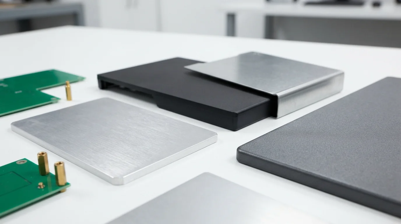
Material selection should follow the enclosure’s mechanical, thermal, electrical, visual, and regulatory requirements. Choosing a material only because it appears in a prototype can create problems when the production process changes. The prototype material is evidence for one design question; it is not automatically the correct production material.
Plastic enclosures
Plastic housings are often selected when low weight, integrated clips or bosses, electrical isolation, and molded appearance are important. The design review should consider wall-thickness transitions, ribs, bosses, snap fits, draft, shrinkage, weld lines, and the location of the parting line. Transparent windows, light pipes, and soft-touch areas may require separate material and process decisions.
Metal enclosures
Aluminum can support a lightweight machined or formed housing with a premium appearance and useful thermal behavior. Steel and stainless steel may be considered when stiffness, wear resistance, or environmental durability has greater priority. For metal parts, review feature sizes, bend radii, tool access, burr control, joining, grounding, and the intended surface treatment.
Finishes are part of the specification
Finish requirements should be written so a manufacturer can inspect and reproduce them. “Premium black” is not a complete specification. A better brief identifies the process, color reference, gloss or texture expectation, visible surfaces, masking areas, logo treatment, and acceptable cosmetic limits. The same finish can look different on molded plastic, machined aluminum, and fabricated sheet metal.
Finish selection also affects assembly. Paint thickness can change a snap fit or threaded connection; anodizing changes the surface of aluminum; blasting changes texture; and a textured mold surface can affect draft and part release. Finish review belongs in the enclosure DFM process rather than at the end of production.
How does an enclosure move from prototype to production?
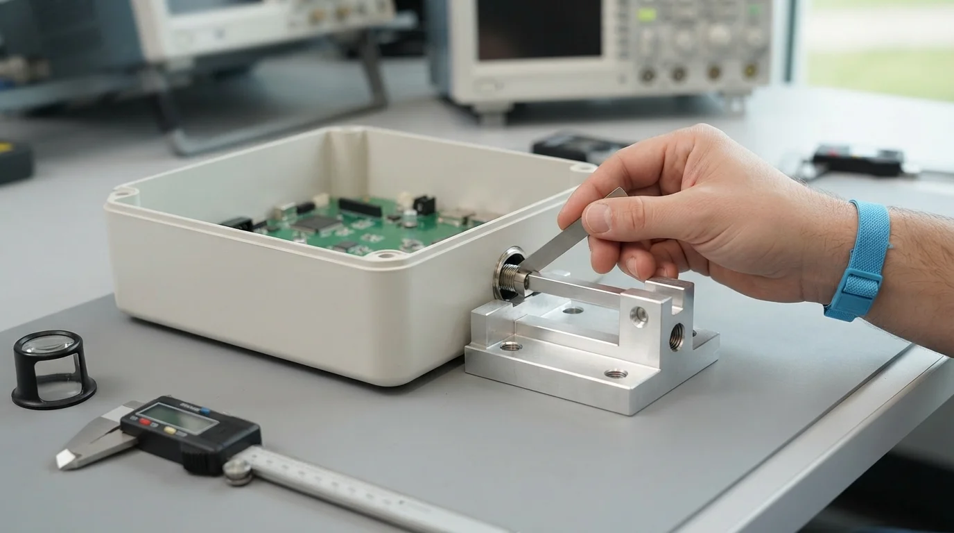
A reliable prototype-to-production enclosure workflow separates design learning from production commitment. Each stage should answer a defined question and produce evidence for the next decision.
- Freeze the product requirements. Record the board envelope, interfaces, battery or power source, expected environment, user touch points, target appearance, quantity, and assembly constraints.
- Build the mechanical package. Bring the PCB, connectors, display, cables, fasteners, and mating parts into the enclosure CAD assembly. Check clearances and service access before refining cosmetic details.
- Run a process-specific DFM review. A design suitable for CNC machining is not automatically suitable for injection molding or sheet metal. Review walls, draft, tool access, bend relief, ribs, bosses, split lines, and joining for the selected route.
- Prototype the highest-risk features. Test connector alignment, button feel, display fit, heat path, sealing interface, drop-sensitive corners, and assembly sequence.
- Validate the production transition. Confirm whether the prototype material, finish, and joining method represent the intended production part. If not, plan a pilot or bridge stage.
- Control revisions and inspection. Use a controlled CAD or drawing revision, agreed critical dimensions, cosmetic samples where relevant, and a first-article review before repeating the order.
The goal is not to make every prototype identical to the final part. The goal is to make each prototype answer a question that matters to the production decision. A fast visual model, a precise machined housing, and a molded pilot part can all be valuable when their purposes are clearly defined.
What should an RFQ package include?
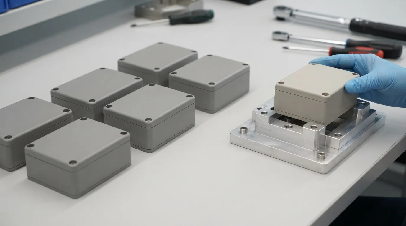
A useful RFQ for a custom electronics enclosure gives the manufacturer enough information to evaluate both the part and the manufacturing route. Sending only a rendered image usually produces a broad estimate and leaves important assumptions unresolved.
| RFQ item | What to provide | Why it matters |
|---|---|---|
| 3D CAD and drawings | STEP or native CAD files, critical dimensions, tolerances, and revision level | Allows assessment of geometry, tool access, and inspection requirements |
| Electronics reference | PCB outline, connector locations, display and battery envelopes, and mating components | Reduces the risk of quoting an enclosure that cannot be assembled around the hardware |
| Material and finish | Preferred material, alternatives, visible surfaces, color or texture reference, and masking needs | Separates a functional prototype quote from an appearance-controlled production quote |
| Quantity and timing | Prototype quantity, pilot quantity, expected annual volume, and delivery milestones | Determines which process should be compared |
| Quality and testing | Critical dimensions, fit checks, cosmetic expectations, environmental tests, and inspection records | Aligns the quotation with acceptance criteria |
Ask the manufacturer to separate one-time costs, unit costs, finishing, assembly, inspection, and shipping assumptions. If several processes are plausible, request a short comparison rather than choosing a process before the design review. A transparent quote should make clear which assumptions would change the price or schedule.
Frequently Asked Questions
What is the best process for a consumer electronics enclosure prototype?
There is no universal best process. 3D printing is useful for early form and fit checks, CNC machining is useful when dimensional accuracy or a metal prototype matters, and vacuum casting can help evaluate a small batch of appearance parts. The choice should follow the specific risk being tested.
Should an electronics enclosure be designed before the PCB is finished?
The enclosure and PCB should be developed together, even if both designs continue to change. The enclosure team needs the board outline, connector locations, component keep-outs, battery envelope, and fastening points to avoid late fit problems.
When does injection molding make sense for a consumer product enclosure?
Injection molding becomes more attractive when the enclosure geometry, plastic material, expected quantity, and appearance requirements justify the tooling investment. Review draft, wall thickness, ribs, bosses, parting lines, and ejection before releasing the mold.
What causes enclosure manufacturing delays?
Common causes include incomplete CAD or drawing information, unresolved PCB changes, unclear cosmetic standards, late material changes, unrealistic tolerances, and selecting a process after the exterior design is fixed.
Final decision guide
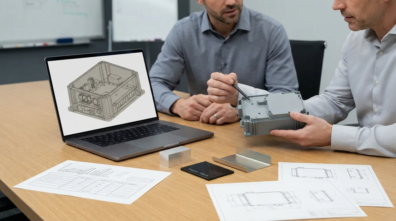
Choose the enclosure process by matching the product risk to the manufacturing method. Use additive prototypes to learn about form and fit, machining when precision or a metal prototype is central, sheet metal when a folded metal structure is appropriate, and molding when repeatable plastic production justifies tooling. If the product is moving between stages, define what must remain constant—fit, interface position, appearance, material behavior, or assembly—before changing processes.
For a manufacturing review, prepare the CAD assembly, electronics reference, target quantity, material and finish requirements, critical dimensions, and validation plan. That information allows a supplier to recommend a realistic route for a prototype, pilot batch, or production enclosure instead of quoting an isolated part without its engineering context.
For additional process background, see the enclosure design and manufacturing guidance from 3DDFM, the process-selection overview from Protolabs, and the electronics enclosure manufacturing overview from Sanmina. These sources support the general engineering principles; the final material, tolerance, and process decision must be verified against the individual product design.

