


Aircraft brakes are often discussed as a system, while a purchase order may cover only a rotor, piston, backplate, torque tube, housing or another build-to-print component. That mismatch between system language and part-level scope creates avoidable quote gaps. A useful manufacturing review begins by mapping what the component must interface with, what the supplier is actually being asked to make, and what acceptance evidence belongs to the part versus the complete brake assembly.
This is a supplier-handoff article for new components and prototypes. It is not a brake maintenance procedure, a design approval or an operational safety instruction. Program drawings and approved engineering authorities define materials, limits and acceptance.
- Define which part of the brake system is in scope
- Trace the load and heat paths into the interfaces
- Choose processes for the actual component family
- Separate part inspection from assembly testing
- Write an RFQ that keeps responsibility clear
- Frequently asked questions
Define which part of the brake system is in scope
Aircraft braking assemblies can include multiple mechanical and friction-related components. Supplier pages for aerospace brake manufacturers describe examples such as brake discs, backplates, torque tubes, sleeves, pistons and related landing-system hardware. The list is not a universal bill of material; the actual architecture depends on the aircraft and program.
Write the order boundary in plain language: one machined housing, a matched pair of parts, a prepared subassembly or a complete brake module. Identify who supplies fasteners, seals, friction elements and purchased components. State whether the supplier performs only machining or also a defined finishing, assembly or inspection step. A quote that uses the same product noun can still cover very different work.
This topic is distinct from a general landing-gear component readiness review: the focus here is the braking assembly’s component interfaces and manufacturing evidence. For the broader aerospace context, the Aviation & Aerospace manufacturing page describes the industry-level routes without replacing the part drawing.
Trace the load and heat paths into the interfaces
Brake hardware participates in mechanical force transfer and thermal exposure, but an individual part does not carry every system requirement by itself. The drawing should identify the features that locate the part, transfer load, maintain a gap, retain another component or establish contact. The assembly definition should identify relevant interfaces among the rotor or disc stack, support structure, actuator components and attachment hardware.
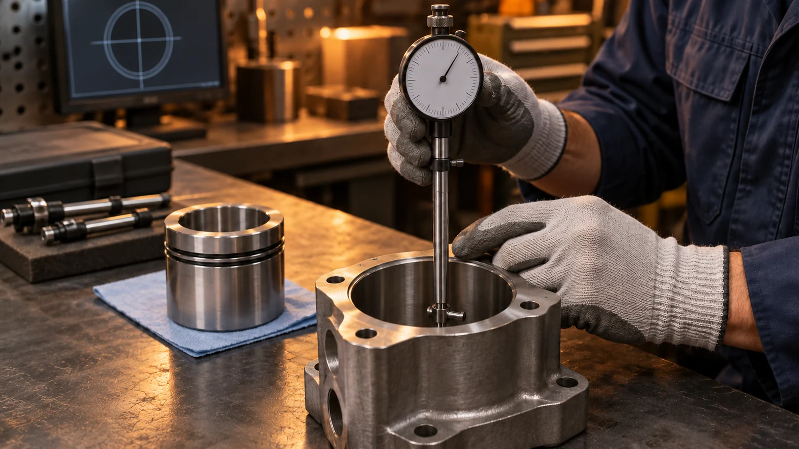
For a machined piston or housing, review bores, ports, threads, sealing surfaces and mounting faces. For a torque tube or backplate, examine attachment patterns, contact faces and datum relationships. For a disc or other friction-related part, the responsible design data must specify the material and surface requirements; a shop should not infer them from a generic brake description.
| Component family | Interface to define | Manufacturing handoff risk |
|---|---|---|
| Piston or actuator housing | Bore, seal surface, port and mounting datum | A local dimension passes while the assembly axis shifts |
| Backplate or support | Attachment pattern and contact face | Fastener access or stack-up is not represented in the drawing |
| Torque tube or sleeve | Axis, spline or key interface and support location | Re-clamping changes the relationship between ends |
| Disc or friction component | Specified friction surfaces and material condition | Machining or finishing changes a controlled surface |
Do not add assumed thermal loads or dimensional targets to a quote request. Instead, provide the design-defined material condition, finish, testing and acceptance limits. If those are missing, route the question to the responsible engineering authority.
Choose processes for the actual component family
CNC turning, milling, drilling, grinding, forming, finishing or assembly may appear in different brake-component routes. The correct mix depends on component geometry, specified material, production stage and required evidence. A piston housing and a friction disc do not share the same process logic simply because both are aircraft brake parts.
For each part, review tool access, setup transitions, chip or burr control, finish requirements and measurement access. A deep bore may need a clearly defined inspection method. A cross-feature or small passage may require an explicit cleanup and verification requirement. A large contact face may need a measurement strategy that matches its datum reference. These questions should be resolved from the released drawing, not a generic promise of precision.
Supplier capability references can show that aerospace brake manufacturing commonly combines machining, fabrication and assembly. For example, NMG Aerospace describes precision machining and assembly of brake system components. Such examples show the range of possible supply scopes; they do not establish the scope or certifications of any other company.
Separate part inspection from assembly testing
Part inspection answers whether the specified dimensions, material records and process requirements were met for the supplied item. Assembly or system testing answers different questions. A CMM report for a housing does not prove brake torque, thermal behavior, stopping distance, fatigue life or aircraft approval. Keep those boundaries visible in the purchase specification and in the final records.
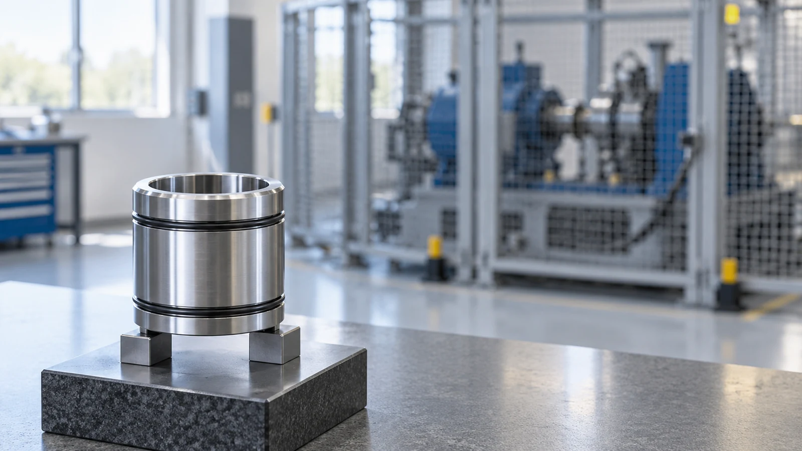
For a component order, list the required characteristics, measurement method, report format and drawing revision. Identify whether material certification, special-process records or first-article documentation are required by the program. Do not request a generic certificate while leaving unclear which part, lot, process or revision it must cover.
For a prototype, specify the question it should answer: fit of an interface, access for a fastener, packaging, a manufacturing route or another limited objective. A prototype built for geometry review should not be described as performance evidence. If assembly or functional testing is required, name the fixture, test owner and approved procedure separately.
Write an RFQ that keeps responsibility clear
A brake component RFQ is strongest when it contains the released drawing and model, material and condition, quantity, finish, special processes, inspection requirements, documentation, packaging and revision status. Add a scope statement naming every included and excluded operation. If the buyer expects matched parts, identify the pairing method and labels required.
- Identify the component and its position in the assembly.
- Show controlled datums and mating interfaces.
- State the approved material, condition and finish.
- List inspection evidence required for the component itself.
- Separate machining, assembly and system testing scopes.
- Record open assumptions before price and schedule are accepted.
Before release, ask the supplier to highlight geometry or inspection risks, including thin sections, access limitations, burr-sensitive intersections and datum transfers. The purpose is early clarification, not delegation of design authority. Any deviation must go through the program’s change-control route.
Frequently asked questions
Does aircraft brakes mean the complete brake assembly?
Not necessarily. A search or RFQ can refer to the complete system, an assembly or one component such as a housing, piston, backplate, disc or torque tube. The purchase scope should name what is included and which party owns assembly and testing.
Can machining inspection prove brake performance?
No. Dimensional inspection can establish only the specified part characteristics it measures. Brake performance or aircraft-level validation requires separate tests and acceptance criteria defined by the responsible program.
Should a supplier choose the material for a brake part?
The supplier can review manufacturability and identify questions, but the approved design definition controls material and condition. A proposed substitution needs formal engineering review and approval before use.
Practical takeaway: aircraft brake work becomes easier to quote when system function is translated into a clear component boundary, controlled interfaces and separate part-level versus assembly-level evidence.

