


Why automotive teams use overmolding
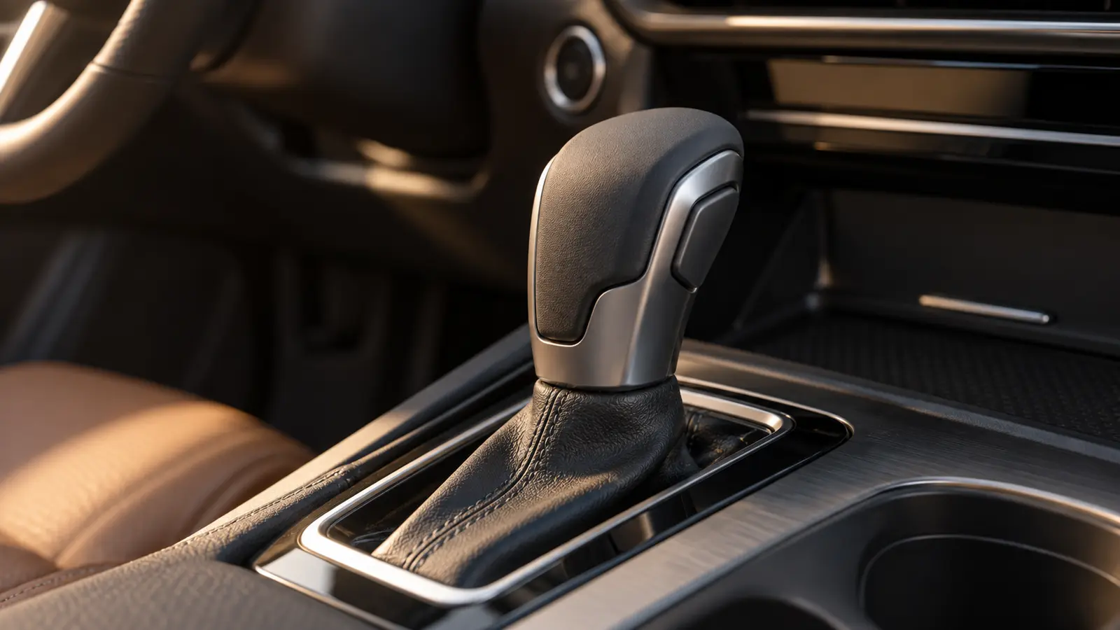
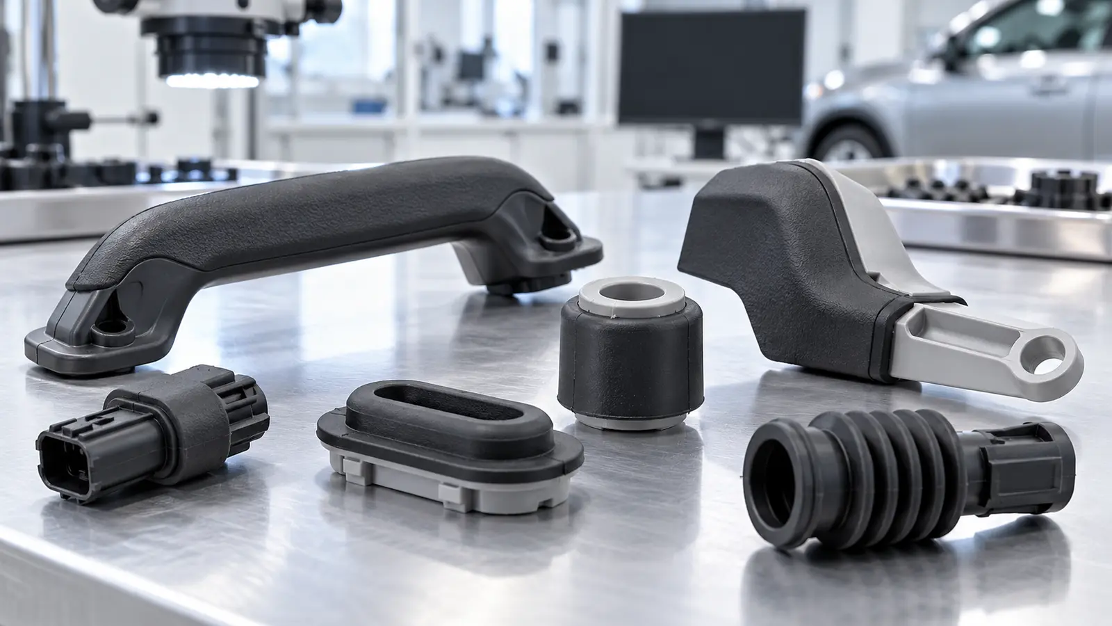
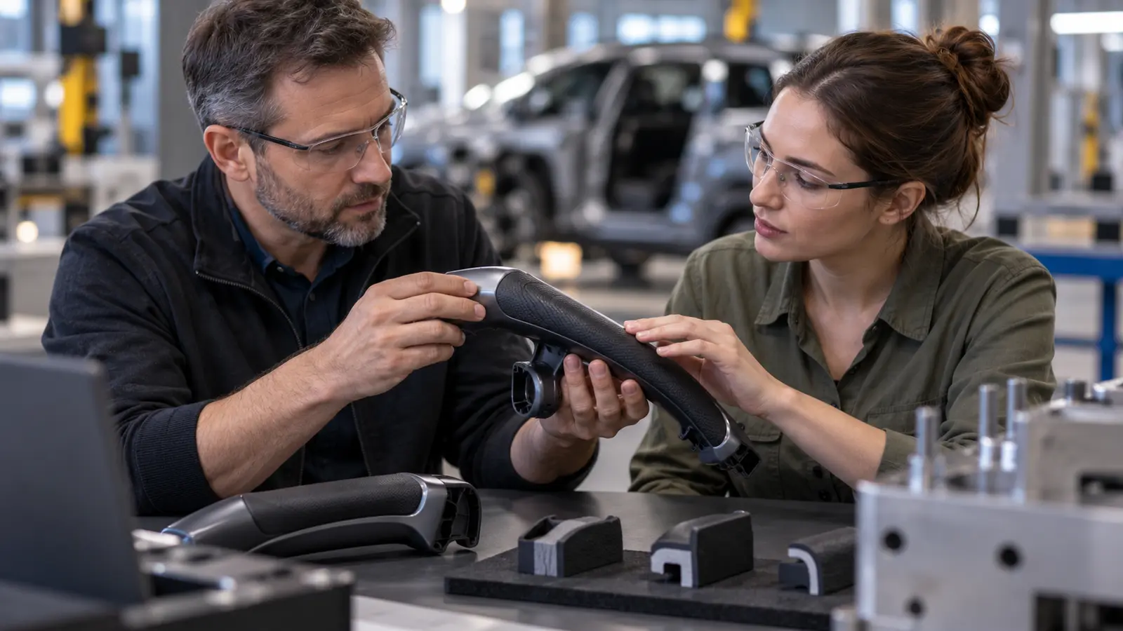
The outer material can provide grip, sealing, insulation, impact protection, or noise reduction, while the inner substrate supplies stiffness and dimensional control. Typical concepts include handles, switches, connectors, sensor carriers, cable protection, and protective edges.
When geometry is still changing, the automotive rapid prototyping workflow can help validate the carrier and soft layer as an assembled product rather than as two unrelated parts.
Build a reliable bond zone
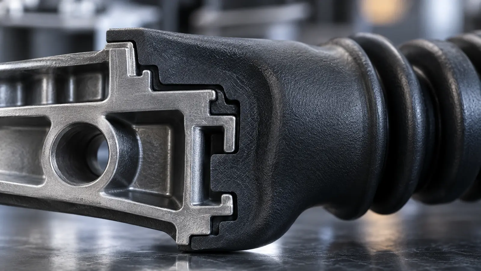
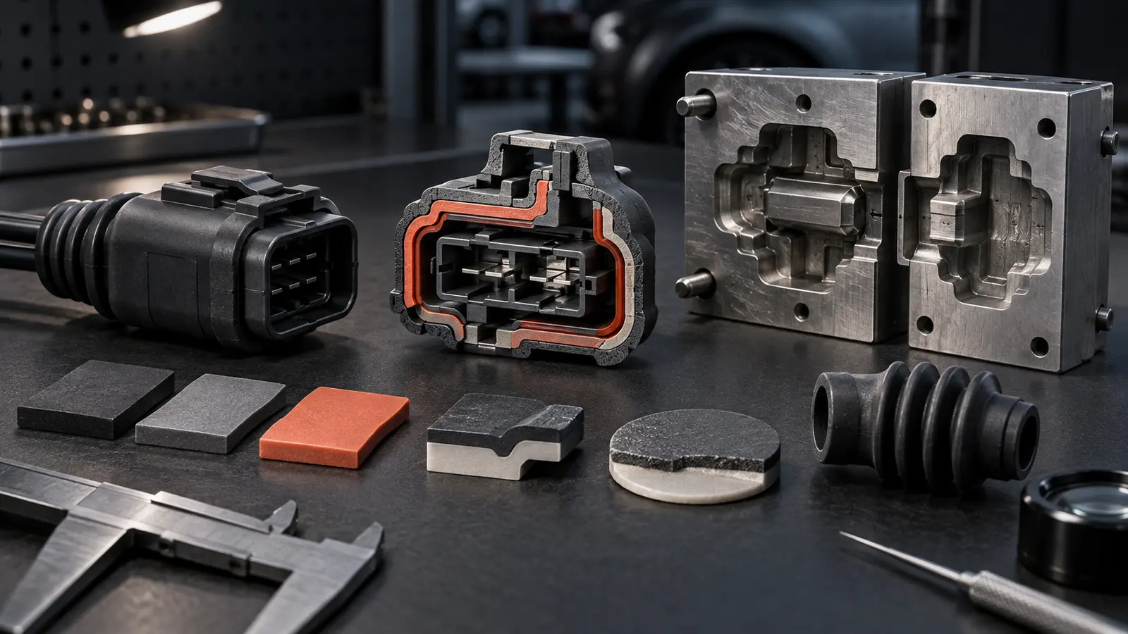
Bonding may be chemical, mechanical, or a combination. Surface cleanliness, texture, undercuts, holes, ribs, and material compatibility all matter. A large flat interface is not automatically strong; it may allow air entrapment or peel loading. Design the interface so the expected force is carried in shear or compression where possible.
| Rischio | Design response |
|---|---|
| Peel at an edge | Use a wrapped edge or mechanical lock |
| Carrier movement | Add locating features and stable supports |
| Air entrapment | Review vents, flow direction, and gate location |
| Material incompatibility | Confirm chemistry and trial the interface |
Choose the molding sequence
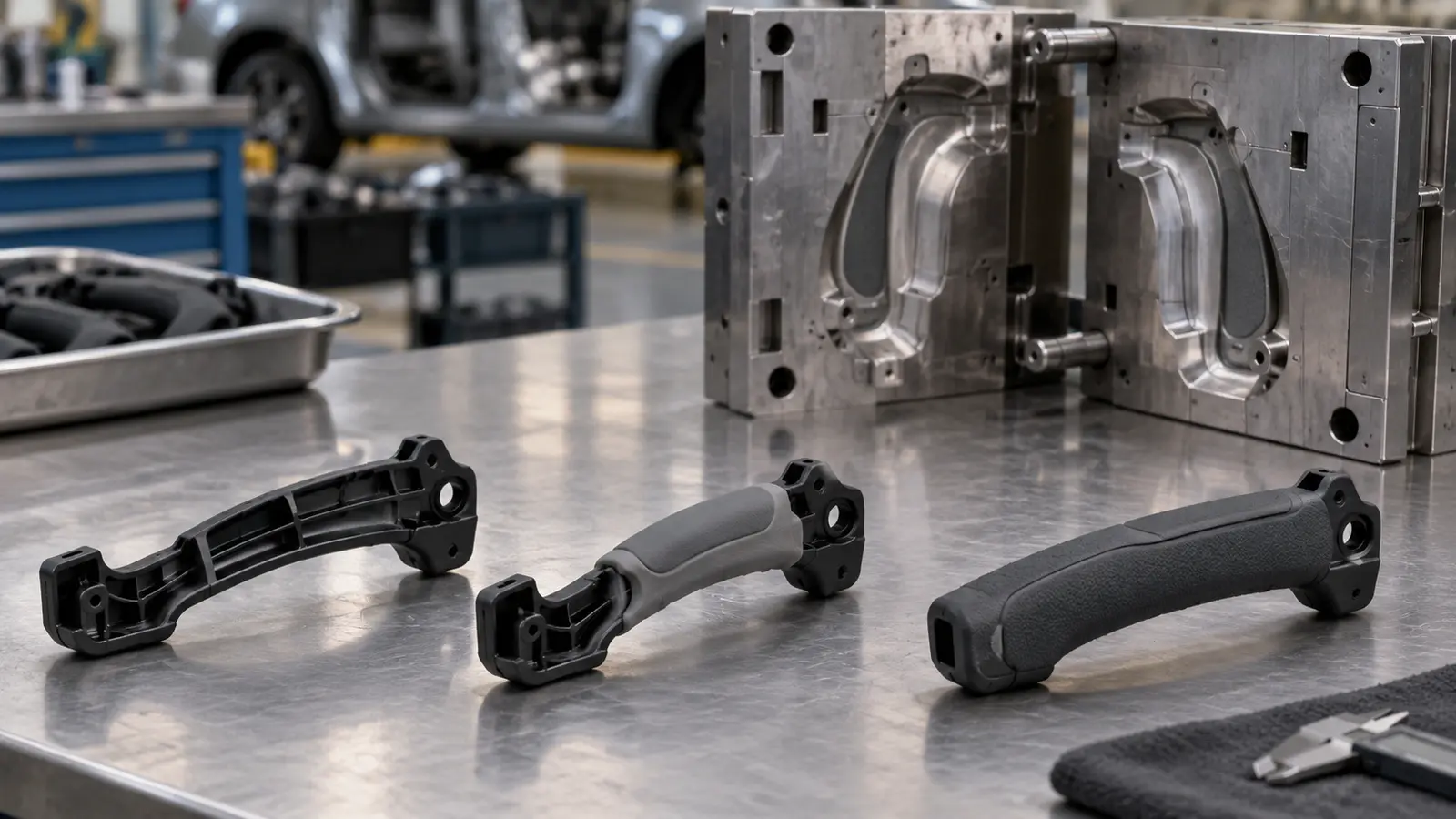
Two-shot molding, insert-based overmolding, and separate molding with later assembly each create different tooling and quality requirements. The decision depends on quantity, material pair, precision, appearance, and whether the substrate can tolerate heat and pressure.
Il low-volume injection molding service is a practical route for functional trials when the team needs to evaluate the interface before committing to a high-volume tool.
Read common failure modes
- Delamination often points to contamination, incompatible materials, or insufficient mechanical retention.
- Warping may come from uneven cooling, different shrinkage, or an unbalanced substrate.
- Flash can indicate parting-line movement, excess pressure, or poor shutoff design.
- Surface blemishes may result from trapped air, moisture, or an unstable flow front.
Testing should reproduce the real use condition: pull, twist, heat, moisture, vibration, chemical contact, or repeated actuation. A simple visual check cannot represent every interface failure.
What to include in a quotation request
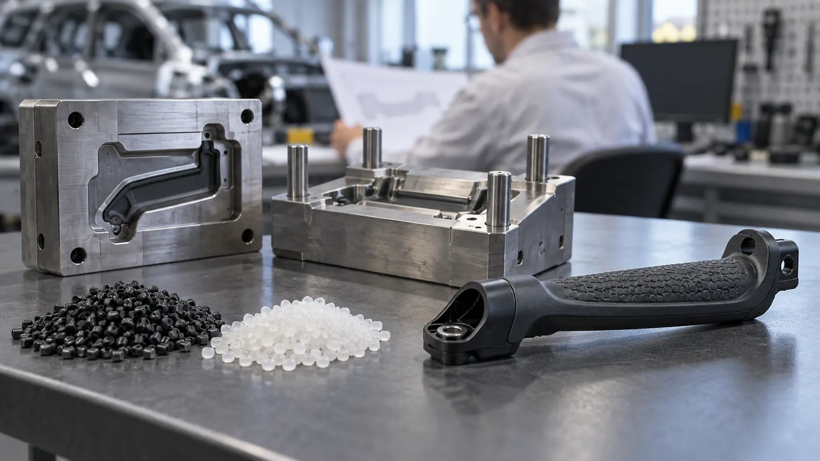
Provide the carrier model, soft-material specification, bond requirements, appearance zones, expected quantity, temperature range, chemical exposure, and intended validation tests. Mark areas that must remain exposed and identify whether the carrier is supplied by the manufacturer or by the buyer.
Ask for a proposed molding sequence, insert-location method, sample plan, and any design changes needed for draft, vents, shutoffs, or retention. This turns overmolding into a controlled engineering decision.
Frequently Asked Questions
What is the difference between insert molding and overmolding?
Insert molding surrounds a preplaced insert with polymer; overmolding commonly adds a second material over an existing substrate. In practice, the terms can overlap, so the material sequence should be stated clearly.
Can rubber-like materials be overmolded onto metal?
Yes, if the substrate, surface condition, polymer, temperature, and retention design are compatible.
Why does overmolding peel?
Contamination, weak retention geometry, unsuitable chemistry, peel loading, or poor process control can all contribute.
Is overmolding suitable for low quantities?
It can be, especially for functional prototypes and low-volume programs where the interface itself must be tested.
A closer engineering review of automotive overmolding
The manufacturing route should be selected from the function of the automotive part, the quantity required, and the evidence the development team needs. A prototype used only for packaging can tolerate different material and surface variation from a part used in a temperature, vibration, torque, or sealing test. Defining that difference at the beginning prevents a visually convincing sample from being interpreted as production-equivalent evidence.
Start with the interfaces. Identify mounting faces, locating holes, clips, seals, fasteners, connectors, moving surfaces, and areas that operators or service technicians must reach. Then mark the critical datums and calculate the tolerance chain between the part and its mating components. This is where many automotive prototypes fail: the individual part is acceptable, but the assembled relationship is not.
Material selection should follow the environment. Consider stiffness, impact resistance, thermal expansion, chemical exposure, moisture, abrasion, electrical requirements, and appearance. If the prototype material differs from the production material, record the difference in the test plan. A material name alone does not define performance; grade, process, orientation, finish, and exposure history can all affect the result.
Design for manufacturing also includes secondary operations. Review trimming, drilling, tapping, machining, deburring, cleaning, coating, painting, assembly, and inspection before the first order. These operations can change dimensions and surface behavior. Critical features should be inspected after the final operation that can affect them, not only after the primary manufacturing step.
| Decision | Information to provide | Useful output |
|---|---|---|
| Processo | Geometry, quantity, material target | DFM review |
| Qualità | Critical features and acceptance | Inspection plan |
| Validation | Load and exposure conditions | Test report |
| Handoff | Revision and traceability needs | Production learning |
A good supplier review should explain what can vary, how it will be measured, and which features require special handling. Ask for assumptions about orientation, support, gate or flow behavior, insert location, tool access, finishing, and packaging where relevant to automotive overmolding. The purpose is not to demand unsupported numbers. It is to make every important assumption visible before parts are made.
Testing should reproduce the real use condition as closely as the prototype purpose allows. Check installation cycles, torque, movement, temperature, vibration, moisture, chemical contact, and service access as appropriate. Photograph failures, record measurements, and connect each result to a design feature or process step. A failed prototype is useful when it narrows the next decision.
For low-volume programs, flexibility is valuable because the model may change. That flexibility should still be controlled through revision numbers, approved material records, first-article checks, and a clear distinction between cosmetic samples and functional samples. When the design stabilizes, compare the prototype route with the intended production process and document which properties need to be revalidated.
An RFQ should include the CAD model, drawing, quantity, material preference, finish, mating components, critical datums, test objective, inspection method, packaging requirements, and delivery stages. Include photographs or marked-up views when a surface, interface, or assembly action is difficult to understand from the model. Clear input reduces avoidable clarification cycles and makes the quote more useful to engineering.
How should the first sample be judged?
Judge it against the stated validation question, the approved drawing, and the declared material and process limitations. Do not use a visual pass as evidence of strength, thermal performance, or long-term durability unless those properties were actually tested.

