


An arthroscopic shaver blade is a small rotating assembly, but its performance envelope is defined by a chain of geometric relationships: the inner cutter must move within the outer tube, the window must expose the intended cutting edge, and the proximal interface must transmit rotation without introducing unwanted runout. For a contract manufacturer, the useful question is not simply which machine can make the blade. It is how the drawing translates into a sequence that preserves edge geometry, concentricity, and assembly fit.
This guide treats arthroscopic shaver blade manufacturing as a customer-defined production problem. It does not make clinical-performance claims or prescribe a device design. The device manufacturer owns design validation and acceptance criteria; the machining partner can help identify process risks, datum choices, inspection access, and documentation needs before the first part is cut.
For wider context, see our medical device manufacturing and prototyping capabilities. The sections below focus on the cutter, sleeve, opening, and interface features that make a shaver blade assembly different from a generic turned component.
Start with the assembly architecture
Before selecting operations, separate the design into the outer tube or sleeve, inner rotating member, cutting window, proximal drive connection, and any features used for retention or alignment. Some designs use a tubular outer member with a shaped opening; others may use a different architecture. The process plan must follow the released drawing rather than assuming a common construction across products.
Create a feature map that identifies which surfaces establish rotation, which dimensions govern the running clearance, and which edges define the cutting profile. Add datums and inspection methods beside each critical characteristic. If a feature is controlled only by a note or an image, resolve its meaning with the design authority before programming; interpreting an unstated edge angle or clearance can create a part that looks plausible but does not match the approved definition.
| Feature group | Planning question | Useful evidence |
|---|---|---|
| Outer sleeve | Which straightness, wall, and interface dimensions are controlled? | Setup references and measurement method |
| Inner cutter | What profile, runout, and edge requirements are specified? | Profile inspection and rotation reference |
| Window and edge | How are edge form, burr limits, and orientation defined? | Optical or magnified inspection criteria |
| Drive interface | How is torque transfer and angular location controlled? | Fit, position, and assembly check records |
Treat the window and cutting edge as one feature group
The opening and edge cannot be planned independently. Window length, width, corner radii, angular orientation, and edge profile may all affect how the inner and outer members meet. A milling cutter, laser process, wire EDM, grinding step, or a combination may be suitable depending on the material, wall thickness, access, and drawing requirements. The method should be chosen for the resulting geometry and edge condition, not because it is familiar or fast in isolation.
Thermal processes can alter a thin edge or nearby material condition, while mechanical cutting can leave a burr or raise a lip at the window. Define the permitted edge break and burr criteria on the drawing or approved specification. If the drawing is silent, request clarification rather than selecting a value. A deburring operation must remove unacceptable material without rounding a functional edge beyond its defined profile.
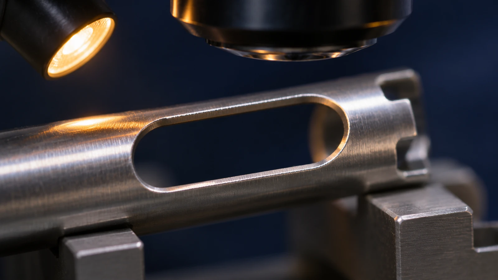
On prototype builds, inspect the opening after the process that creates it and again after any finishing operation that can change the edge. Record the orientation reference so a reviewer can distinguish a dimensional issue from a clocking issue. Magnified visual inspection may help assess edge quality, while optical measurement can establish profile or position when the acceptance plan calls for it.
Protect concentricity through the operation sequence
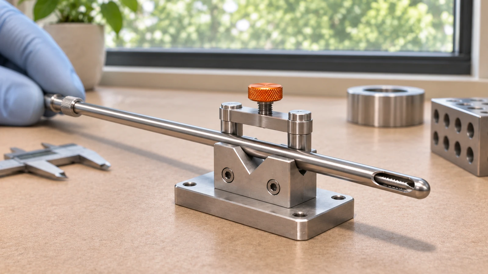
The inner and outer members need a controlled relationship for assembly, but the relevant tolerance must come from the design. Turning, drilling, tube sizing, milling, grinding, and secondary finishing can each influence roundness, straightness, or runout. A long thin tube is also sensitive to clamping force and support spacing. Workholding should support the part near the cutting load while avoiding distortion that disappears when the part is released.
Sequence operations so that important reference surfaces are created early and reused consistently. If the window is cut after the tube is finished, make sure the fixture references the same axis and orientation used for the critical diameter checks. If a later operation changes the surface or edge, identify which dimensions need remeasurement. A simple control plan can list each setup datum, operation, potential source of movement, and verification point.
The proximal drive interface deserves its own setup review. A keyed, slotted, or otherwise shaped connection may have angular position and fit requirements relative to the cutter window. Inspecting the interface alone does not prove its relationship to the distal geometry. Use a shared datum strategy or a dedicated fixture that carries the relationship through the part length, as required by the drawing.
Choose cutting and finishing methods by geometry
CNC turning can establish cylindrical members and concentric features; milling can create flats, slots, and selected windows; drilling or boring may form specified internal passages. Grinding or other finishing can be considered when surface or edge requirements call for it. For early design iterations, precision CNC machining e produzione di prototipi can help evaluate fit and manufacturability before the process is locked.
Material selection is controlled by the device specification. Stainless steel is common in many instrument designs, and some designs may specify titanium or another alloy. Each material changes tool choice, cutting behavior, surface response, and deburring effort. The purchasing record should identify the exact grade and condition rather than relying on a generic “medical stainless” description. See the site’s stainless steel machining information for general process context; it does not replace the customer’s material callout.
Surface finishing and cleaning should be tied to a written requirement, including which surfaces are treated, what appearance or measurable condition is expected, and what post-process inspection is needed. A finish name alone may not define roughness, edge condition, or cleanliness. Do not assume a polished appearance proves a particular surface value.
Build inspection around motion and interface
Inspection should cover the features that define fit and motion: inner and outer diameters, runout or concentricity where specified, window geometry, edge condition, and drive-interface relationship. Use pins or air gauges only for the characteristic they are suited to verify. Optical comparators, microscopes, CMMs, or custom gauges can be considered depending on the dimensions and approved plan. State the method and datum setup in the record so results are repeatable.
If assembly checks are part of acceptance, define what constitutes the check and how it is recorded. A fit check can reveal interference or inconsistent movement, but it does not replace dimensional verification of specified characteristics. For a prototype, the customer and supplier should agree on sample size, feature priorities, inspection report format, and disposition of any deviation before production begins.
Cleaning and packaging instructions should also be explicit. Clarify whether parts must be protected from contact damage, separated to prevent edge-to-edge contact, or delivered with traceability documents. The applicable requirements depend on the customer’s quality system and product definition; do not infer sterility or clinical readiness from a machining or cleaning step.
What to include in a shaver blade RFQ
A useful RFQ package includes the controlled drawing and revision, exact material grade and condition, quantity and forecast, required finish, critical-to-quality features, inspection reporting expectations, and any approved special processes. Include an assembly model or interface drawing when the inner and outer components must work together, and identify the datum scheme used to evaluate their relationship.
- Identify inner and outer member geometry and any supplied mating parts.
- Call out edge, burr, concentricity, straightness, and interface requirements explicitly.
- State the material condition, finish, cleaning, packaging, and traceability requirements.
- Define prototype acceptance evidence and how drawing questions or deviations are approved.
These details help a supplier quote the actual manufacturing and inspection scope rather than a simplified part description. They also reveal whether the most important risk is edge formation, long-part support, assembly clearance, or documentation.
FAQ
Can one process create every shaver blade feature?
Usually the route is selected by feature and material. Turning, milling, drilling, grinding, EDM, or laser processing may be combined where the drawing supports them. There is no universal sequence for every design.
Which dimensions should be checked first?
Prioritize the specified relationships that control assembly: the running surfaces, window profile and orientation, drive interface, and any stated runout or straightness characteristics. The released drawing and control plan govern acceptance.
Does a clean-looking edge prove it meets the requirement?
No. Visual appearance can identify obvious burrs or damage, but profile, dimensions, and surface characteristics require the measurement methods defined by the specification.
What information helps a prototype quote?
Provide the current drawing, material and condition, quantity, finish, critical features, mating components, and inspection expectations. Clarify whether the quote covers separate components, assembled parts, or both.