


La commercializzazione di successo di nuovi dispositivi hardware richiede un approccio ingegneristico sistematico che affronti precocemente i limiti della produzione ad alto volume. Eseguire il processo di transizione dal prototipo alla progettazione per la produzione assicura che gli assemblaggi concettuali in fase iniziale siano ottimizzati per utensili in acciaio duro e cicli rapidi. Molti team di prodotto incontrano gravi blocchi di sviluppo perché trattano i mockup additivi come file di produzione finali, solo per scoprire che le loro geometrie violano la fisica di base dello stampaggio a iniezione. Eliminare queste discrepanze geometriche durante lo sviluppo previene costose modifiche agli stampi e protegge i budget critici di lancio.

Collaborare precocemente con stampisti esperti aiuta i progettisti meccanici a bilanciare le proprietà dei materiali grezzi con le capacità di alta produttività. Gli specialisti di ingegneria industriale analizzano angoli di sformo, uniformità delle pareti, linee di divisione e posizionamento degli espulsori per convertire modelli visivi in asset di produzione robusti. Simulazioni specializzate rivelano potenziali problemi di flusso del polimero, prevenendo imperfezioni estetiche come segni di ritiro o splay prima di tagliare l'acciaio dello stampo. I gruppi di progettazione assicurano percorsi di produzione stabili ed economici affrontando le regole di scalatura geometrica fin dall'inizio.
Indice
1. Limiti della Stampa senza Presidio rispetto ai Vincoli dello Stampaggio
2. Riprogettazione delle Geometrie Strutturali per lo Stampaggio a Iniezione
3. Scalatura della Produzione Ponte tramite Soluzioni di Utensileria Rapida
Limiti della Stampa senza Presidio rispetto ai Vincoli dello Stampaggio

Domanda: Perché i prototipi stampati spesso falliscono quando inizia la transizione allo stampaggio? La stampa additiva opera senza angoli di sformo fisici o limiti di spessore uniformi, mentre lo stampaggio a iniezione richiede caratteristiche geometriche specifiche per un rilascio pulito.
La stampa 3D SLA offre una straordinaria libertà di progettazione, generando facilmente canali chiusi complessi e caratteristiche verticali senza sformo che sono impossibili da stampare. La fabbricazione di componenti con queste geometrie non vincolate crea una falsa sensazione di sicurezza meccanica durante le prime revisioni concettuali. Lo stampaggio a iniezione si basa sulla divisione fisica dell'acciaio dello stampo e sull'espulsione delle parti in plastica, rendendo obbligatorie concessioni geometriche specifiche per cicli ad alto volume. Richiedere feedback professionale di produzione precocemente impedisce agli ingegneri di bloccare caratteristiche impossibili da stampare.
Non considerare i percorsi di rilascio dello stampo durante lo sviluppo iniziale comporta costi elevati e gravi ritardi nella realizzazione degli utensili. I progettisti di prodotto devono anticipare dove lo stampo si dividerà, assicurando che le linee di divisione non attraversino superfici estetiche critiche. Padroneggiare i dettagli della transizione dal prototipo alla progettazione per la produzione consente ai team di ingegneria di ottimizzare le linee di divisione e ridurre drasticamente il numero di cursori. L'ottimizzazione precoce semplifica la fabbricazione degli utensili e garantisce risultati estetici altamente ripetibili.
Riprogettazione delle Geometrie Strutturali per lo Stampaggio a Iniezione
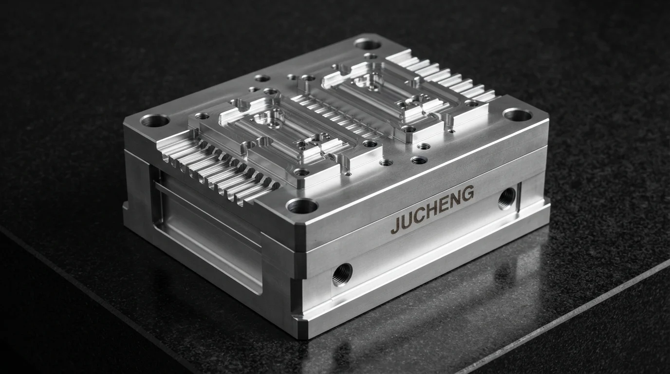
Domanda: Come vengono riprogettate le pareti verticali per un'espulsione pulita delle parti? I progettisti aggiungono angoli di sformo di almeno 1,5 gradi su tutte le caratteristiche verticali per consentire alle parti di scivolare via facilmente dalle cavità in acciaio.
Gli angoli di sformo rappresentano una caratteristica di progettazione fondamentale per le parti in plastica stampate a iniezione, prevenendo trascinamento e abrasione durante i cicli di espulsione. Implementare una progettazione rapida di prototipi I principi assicurano che nervature verticali e mozzi abbiano un angolo di sformo adeguato prima della lavorazione degli stampi permanenti. I diametri dei mozzi vengono generalmente ridotti leggermente verso la faccia aperta per mantenere spessori uniformi e prevenire segni di ritiro estetici. La convalida dimensionale anticipata garantisce che queste caratteristiche alleggerite tengano saldamente le viti autofilettanti.
Aderire ai limiti di spessore uniforme delle pareti è altrettanto vitale, prevenendo il ritiro localizzato del polimero che porta a deformazioni post-stampaggio. Le nervature strutturali sono progettate con uno spessore pari al 60 percento della parete nominale per fornire rinforzo senza causare segni di ritiro sulle superfici a vista. Questa tabella tecnica illustra le differenze geometriche tra prototipazione additiva e standard di stampaggio a iniezione:
| Caratteristica di Progettazione | Baseline di Prototipazione Additiva | Regola di Produzione per Stampaggio a Iniezione | Motivo Ingegneristico Principale |
|---|---|---|---|
| Angolo di Sformo | Senza sformo consentito | Minimo da 1,5° a 3,0° | Impedire il trascinamento del pezzo, consentire una facile espulsione dallo stampo |
| Uniformità della Parete | Spessore parete variabile OK | Variazione massima ±10% | Prevenire tensioni interne, fermare deformazioni post-stampaggio |
| Rapporto Nervatura-Parete | Spessore uguale consentito | Massimo 60% della parete nominale | Eliminare segni di ritiro estetici sulle superfici a vista |
Colmare il Passaggio alla Produzione tramite Soluzioni di Stampaggio Rapido
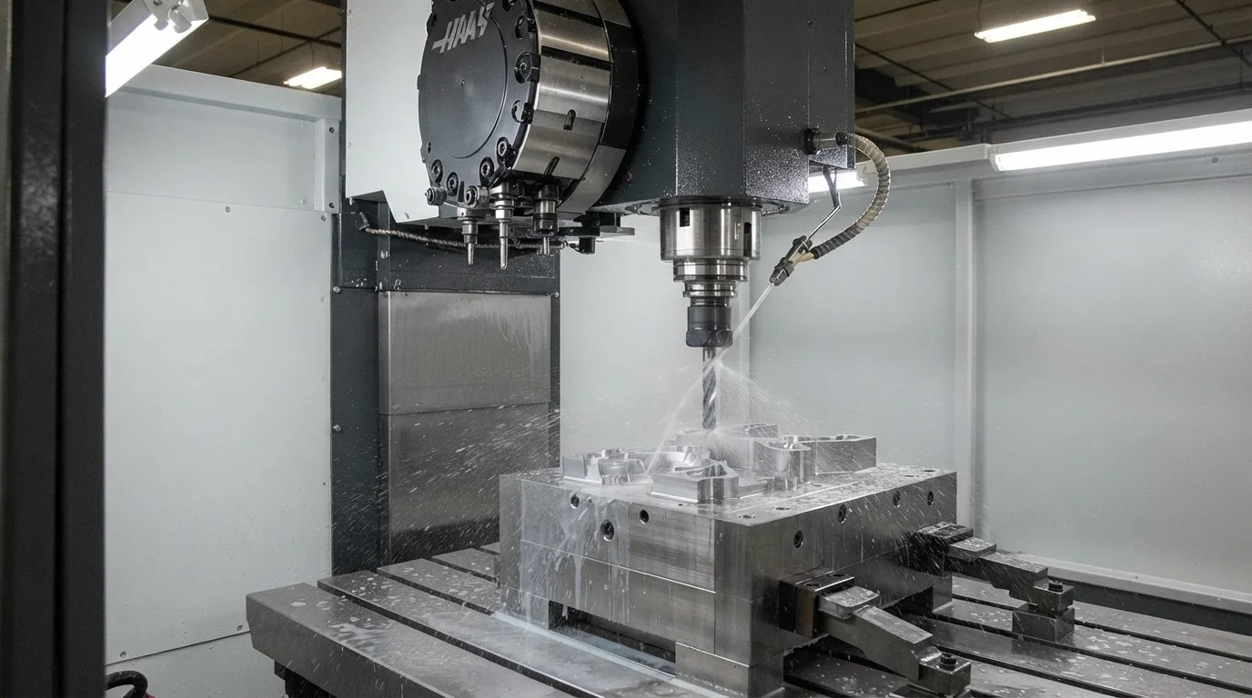
Domanda: Come viene colmato il divario di transizione tra stampi prototipo e stampi ad alto volume? L'attrezzatura rapida in alluminio fornisce una soluzione intermedia ideale, producendo rapidamente migliaia di parti di qualità produttiva.
Investire in attrezzature in acciaio ad alto volume richiede mesi di tempo di fabbricazione e centinaia di migliaia di dollari di capitale iniziale. L'attrezzatura rapida che utilizza inserti di nucleo e cavità in alluminio offre una soluzione ponte eccezionale, producendo fino a 100.000 parti funzionali in poche settimane. L'approvvigionamento di stampi rapidi consente agli sviluppatori di prodotto di validare le proprietà reali del materiale di produzione prima di impegnarsi in acciaio temprato. Gli stampi in alluminio trasferiscono rapidamente l'energia termica, riducendo i tempi di ciclo e consentendo una rapida validazione della produzione.
Eseguire con successo il passaggio dal prototipo al design di produzione comporta la verifica dei comportamenti del flusso di stampo sotto pressioni reali della macchina. Jucheng Precision opera in uno stabilimento di produzione completamente attrezzato con oltre 150 macchine CNC e 35 presse di stampaggio a iniezione di precisione. Le macchine di misura a coordinate automatizzate verificano dimensioni sub-micrometriche per garantire la conformità agli standard ISO 9001 e IATF 16949. I team di fabbrica forniscono certificazioni complete dei materiali per verificare la conformità chimica durante ogni prova.
Gli ingegneri di fabbrica forniscono analisi revisioni DFM gratuite 24 ore su 24 esaustive per risolvere tempestivamente potenziali difetti di colata o segni di espulsione. Gli stampi rapidi specializzati producono componenti stampati a iniezione entro 4-15 giorni, aiutando i gruppi di progettazione a rispettare programmi di lancio aggressivi. Operando con una politica rigorosa senza quantità minima d'ordine, i gruppi meccatronici possono perfezionare in sicurezza variazioni hardware personalizzate.
Domande Frequenti (FAQ)
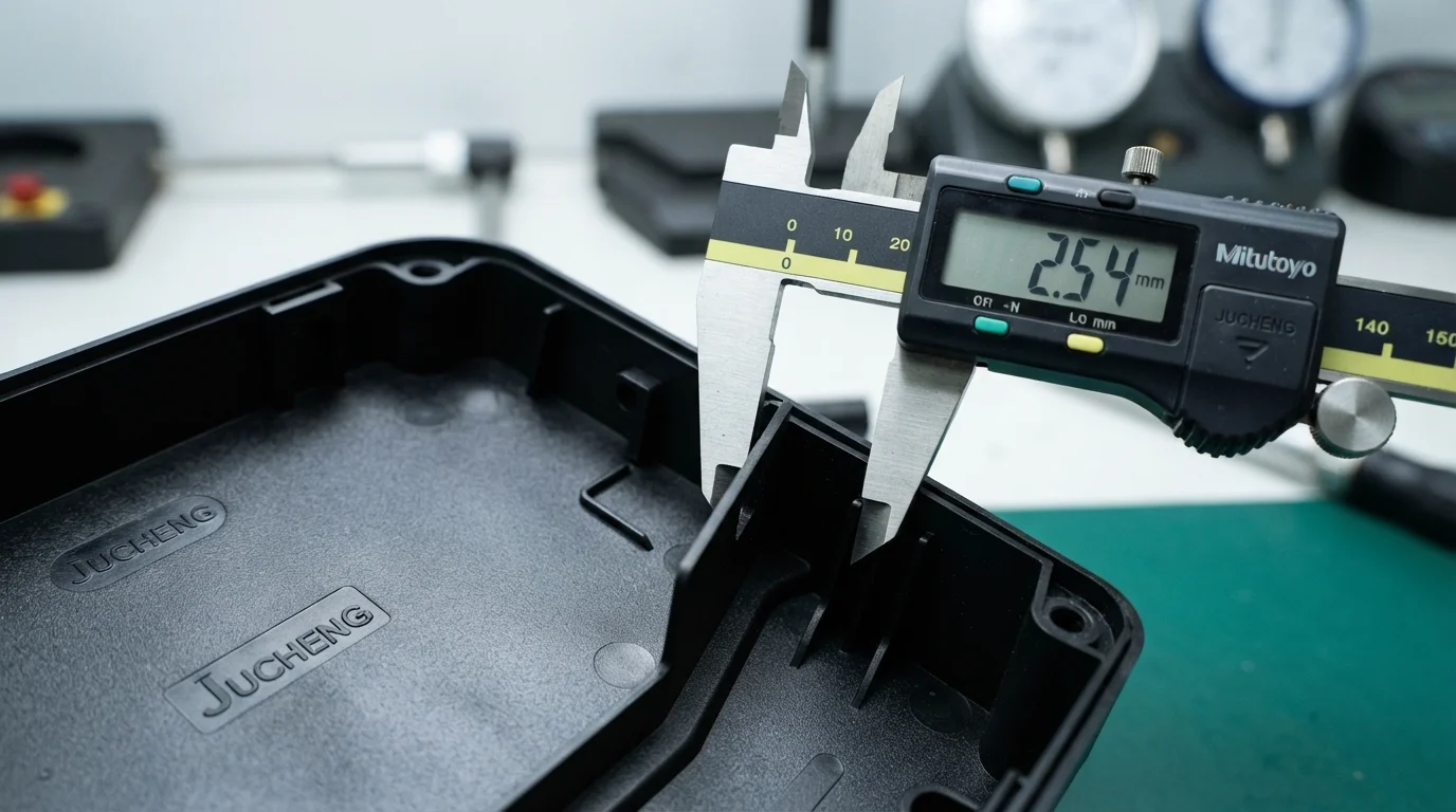
Qual è la modifica di progettazione più critica quando si converte una stampa 3D in una parte stampata a iniezione?
Aggiungere angoli di sformo adeguati rappresenta la modifica più critica richiesta per lo stampaggio. Le pareti verticali devono assottigliarsi leggermente per evitare che la parte trascini contro l'acciaio del nucleo durante i cicli di espulsione.
Perché gli angoli interni acuti sono problematici nei progetti di produzione?
Gli angoli interni acuti creano zone di alta concentrazione di stress, aumentando il rischio di guasto strutturale della parte sotto carichi dinamici. Progettare generosi raggi di raccordo distribuisce uniformemente lo stress meccanico semplificando la lavorazione CNC dello stampo.
Come fa uno stampo ponte a far risparmiare denaro durante il lancio del prodotto?
Gli stampi ponte in alluminio costano una frazione degli attrezzi in acciaio ad alto volume, consentendo agli sviluppatori di testare i mercati e validare i progetti in modo conveniente. Risolvere problemi meccanici su un attrezzo in alluminio previene modifiche estremamente costose sugli stampi di produzione in acciaio temprato.

