


Configuring realistic mechanical limits during the early modeling phase is a fundamental step in ensuring high assembly yields. Utilizing a comprehensive sheet metal tolerance chart allows product designers and procurement managers to align their 3D CAD callouts with physical shop floor capabilities. This visual reference plays a vital role in high-quality sheet metal fabrication, directly determining whether your multi-component enclosures slide together smoothly or bind under structural stresses.
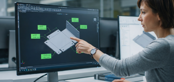
Suffer from unexpected delays and bloated tooling bills when your first prototype runs arrive out of spec? When drawings are modeled with overly tight tolerances that exceed standard press brake limits, it forces operators to slow down feed speeds and run secondary manual adjustments, inflating your labor costs. Aligning your custom designs with standard commercial limits is the best way to secure your product margins.
Let's explore how to read an industrial fabrication chart, analyze the distinct tolerance classes for laser profiling, bending, and hardware insertion, and review how to access our complete DFM guide to optimize your hardware budgets.
How to Use the Fabrication Tolerance Chart
What physical and geometrical factors dictate how you read a standard fabrication chart?
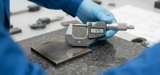
A standard chart categorizes dimensional limits based on material thickness thresholds, alloy hardness, and the specific processing method used to form the part.
To leverage the full physical potential of a sheet metal tolerance chart, engineers must first identify their material class. Harder metals with high tensile limits behave differently under press brakes than soft, ductile alloys. This variance means that a standard linear tolerance of ±0.1mm is highly economical to hold on thin cold-rolled SPCC steel, but extremely difficult to maintain on thick structural plates without secondary processing.
Additionally, our reference charts divide dimensional ranges into specific bands. A linear length under 100mm can easily hold tight tolerances, but as the part length scales past 1000mm, thermal expansion and raw material thickness variations will naturally widen the standard tolerance band. Designers must verify these scale-dependent limits before releasing their 2D PDF drawings to production.
Laser Cutting, Bending, and Hardware Insertion Tolerances
What are the standard commercial and precision tolerance bands for cutting, bending, and inserting hardware?
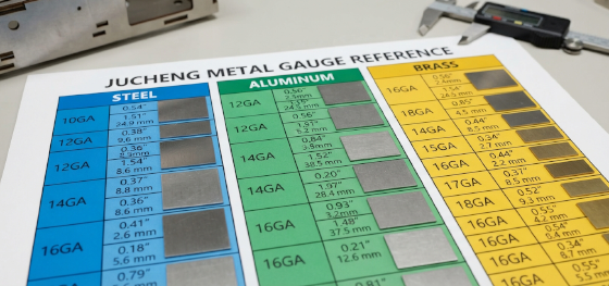
Standard fiber laser cutting holds ±0.1mm, air bending holds ±0.3mm linearly and ±1.0 degree angularly, and automated hardware presses install PEM inserts within ±0.15mm.
To ensure successful component fits, analyzing how different processes introduce dimensional variations is critical. High-speed taglio laser is exceptionally precise because it is a non-contact process that eliminates mechanical tool deflection, allowing us to hold extremely tight cutting tolerances. However, as the parts move to the press brake for folding, material springback and raw thickness variations introduce angular variations. Below is a direct overview of these processing limits:
| Processo di fabbricazione | Tolleranza commerciale standard | JUCHENG Precision Tolerance |
|---|---|---|
| Taglio con Laser a Fibra | ±0,15 mm (Limite standard del taglio laser) | ±0.05 mm (Tight micro-profile) |
| Piegatura con Pressa Piegatrice | ±0,3 mm / ±1,0° (Piegatura ad aria standard) | ±0.1 mm / ±0.5° (Precision bottoming) |
| Hardware Insertion | ±0.25 mm (Manual alignment) | ±0.15 mm (Automated press centering) |
| Turret Punching | ±0,20 mm | ±0.08 mm (Highly consistent hole grids) |
Beyond cutting and bending, executing precise hardware insertion requires dedicated mechanical calibration. When pressing self-clinching PEMnuts, standoffs, or studs into pre-punched holes, maintaining tight positional tolerances (within ±0.15mm) is vital to ensure that mating PCB boards align perfectly with the standoffs during final assembly. We select the optimal process parameters based on your selected aluminum, stainless steel, or carbon steel gauge to maintain total consistency.
Download Our Complete Sheet Metal Tolerance PDF Guide
Where can engineers access a comprehensive, downloadable reference guide for custom DFM limits?
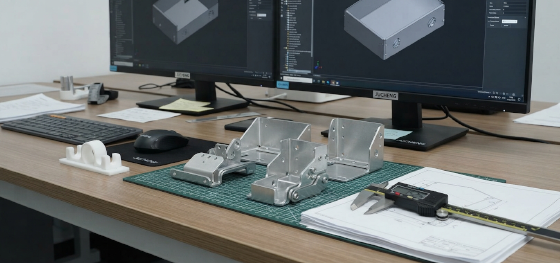
We offer a highly detailed, downloadable PDF guide containing complete linear, angular, and hole-to-edge tolerance parameters to help you optimize your drawings.
Searching the internet for fragmented, inconsistent thickness tables can quickly stall your product development timeline. To support engineering teams worldwide, we have compiled our complete in-house manufacturing limits into a single, downloadable PDF document. This exclusive reference guide contains complete charts for sheet thickness tolerances, minimum bend radii, hole-to-bend safety distances, and flat pattern unfolding parameters.
Integrating these verified manufacturing limits into your active tolleranze per la lavorazione della lamiera database is the single most effective way to eliminate pre-production design errors. It acts as a powerful DFM checklist, helping your team identify unbendable flanges or hole distortion risks before releasing your final models. Click the button below to download the complete PDF guide and optimize your engineering workflows.
Let Our Engineering Team Review Your Tolerances

How does JUCHENG help designers verify and optimize their custom part tolerances?
Our professional technical department reviews your CAD files using advanced DFM software, identifying loose or over-tight tolerances within hours.
Why risk your project budgets on inaccurate automated online estimators? At JUCHENG, our experienced engineering team reviews your 3D STEP or IGES files manually, matching your critical dimensions to our active press lines and clean finishing booths. This human-led review ensures that your overall project tolerances are technically viable and highly repeatable on the shop floor.
We evaluate every aspect of your custom progettazione di lamiere, checking for tool clearances and material grain directions before cutting steel. Supported by our AS9100 and ISO 13485 compliant quality management systems, we manage your project from initial flat pattern cutting to final, high-durability packaging and assembly.
FAQ: Critical Questions About Sheet Metal Tolerance Chart
Il nostro team di ingegneria ha compilato soluzioni professionali per le sfide più comuni di qualità e costo affrontate dagli sviluppatori di prodotti:
Qual è la tolleranza standard per la fabbricazione generale di lamiere?
Secondo le norme commerciali standard (come ISO 2768-m), la tolleranza standard per la fabbricazione generale di lamiere è di circa ±0,3 mm per dimensioni lineari inferiori a 120 mm e ±1,0 grado per pieghe angolari. Questi limiti sono molto convenienti da produrre, ma gli involucri di alta qualità spesso richiedono tolleranze personalizzate più strette fino a ±0,1 mm e ±0,5 gradi, che otteniamo utilizzando stampi di fondo avanzati.Perché acciaio, alluminio e acciaio zincato hanno tolleranze diverse per lo stesso spessore?
Materiali diversi utilizzano sistemi di laminazione grezza separati in fabbrica, con conseguenti diverse tolleranze di spessore grezzo. Ad esempio, una lamiera di acciaio zincato calibro 16 è leggermente più spessa dell'acciaio laminato a freddo standard a causa del suo rivestimento protettivo di zinco. I nostri programmatori calibrano il nostro software di sviluppo utilizzando tolleranze di spessore specifiche per materiale per garantire che i vostri modelli piatti siano tagliati con precisione.Una tolleranza dimensionale stretta aumenta sempre i costi di produzione personalizzata?
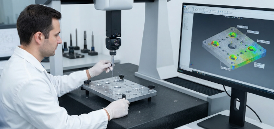
Sì, assolutamente. Richiedere tolleranze più strette dei limiti commerciali standard costringe l'officina a eseguire regolazioni manuali secondarie, rallenta le velocità di avanzamento della macchina e richiede controlli dimensionali CMM continui, aumentando i costi di manodopera. Raccomandiamo di utilizzare tolleranze commerciali standard ove possibile e di specificare tolleranze strette solo per interfacce di accoppiamento critiche.How does JUCHENG prevent thickness variations from affecting the sheet metal tolerance chart limits?
Evitiamo le variazioni delle materie prime acquistando solo bobine di acciaio premium certificate dal mulino con tolleranze di spessore strette. Il nostro team di controllo qualità misura continuamente le lamiere in ingresso utilizzando micrometri digitali calibrati e inserisce queste misurazioni reali nei nostri sistemi CAD di spiegatura, garantendo che i nostri calcoli progressivi e le configurazioni degli utensili siano perfettamente abbinati allo spessore effettivo del metallo.

