


A prosthetic pyramid adapter should be defined by its mating interface, attachment method, material condition, and approved assembly requirements. Similar-looking pyramids are not evidence of interchangeability. The contact faces, receiver, adjustment screws, installation height, and neighboring components form a system that must be evaluated together.
For a development team ordering machined prototypes, the practical task is to express that interface clearly enough to manufacture and inspect. This article focuses on component geometry and process decisions. It does not provide patient fitting instructions, alignment adjustments, clinical recommendations, or a load rating for a custom part. Those decisions require the responsible device manufacturer’s evidence and approved procedures.
Identify the connection being developed
First distinguish a male pyramid, a pyramid receiver, a threaded adapter, a tube connection, and a combined component. Their drawings answer different questions. A male interface needs controlled contact geometry; a receiver adds the relationship between its internal features and adjustment or clamping hardware. A combined part also needs a defined relationship to the second connection.
Provide an assembly model and the controlled mating-component specification. If compatibility with an existing system is intended, establish the authorized interface requirements rather than scaling a photograph or copying nominal dimensions from a retail listing. Product names and descriptions can identify a category but do not provide the tolerances or acceptance criteria needed for a safe interchangeable component.
Record the intended prototype purpose. A display model can answer a packaging question without being suitable for load-bearing use. An interface sample can support dimensional and assembly evaluation without establishing fatigue performance. The distinction should travel with the model, purchase order, sample identification, and inspection report so later teams do not overinterpret the result.
Contact faces and screw locations need a common definition
On a prosthetic pyramid adapter, the pyramid’s faces must be described in relation to the reference that controls the connection. A drawing should express the relevant angles, profiles, heights, and contact boundaries without leaving their relationship to an unspecified model origin. Identify which surfaces locate the assembly and which provide clearance. State how edge relief is treated near a contact region.
For a receiver, define the screw axes and their relationship to the mating geometry. The screw tips, thread engagement, and contact regions depend on the actual system design. A thread that passes a gauge does not establish that its axis points toward the intended surface. Position, orientation, and surrounding section thickness need separate attention where the design requires them.
Review the accessible adjustment and assembly envelope in CAD. A component may fit its immediate mating part while blocking access to a fastener or contacting another component at the required position. Manufacturing review should flag these conditions to the design owner. Any geometry change affecting the connection requires controlled approval, rather than an informal modification to make machining easier.
Installation height is a stack, not one isolated dimension
Available build space can make installation height important. The relevant stack may include a socket attachment, adapter, receiver, tube connection, or another component. Identify the reference planes used to measure the stack and distinguish overall physical height from the height added in the assembled configuration. Different product descriptions can use different conventions.
Ad esempio, Ottobock’s threaded pyramid adapter information describes a connection that screws into a lamination anchor to reduce build height while retaining adjustment possibilities. That is a manufacturer-specific design. Its dimensions and permitted adjustment do not define a universal pyramid interface or authorize substituting a custom component.
When comparing concepts, show a common section through each assembly and use the same reference convention. Include the space required for approved thread engagement, fastener access, and neighboring parts. A shorter external body is not automatically a shorter installed connection. This comparison can prevent a prototype from meeting an isolated dimension while missing the actual packaging goal.
Compare titanium and stainless steel in the specified state
Both material families appear in commercial prosthetic adapters, but their presence in catalogs does not make every grade or geometry interchangeable. Compare the approved material specifications, section design, surface requirements, processing route, and required verification. Mass, corrosion behavior, and manufacturing effort belong in the decision, together with the structural evidence required for the complete component.
Il titanium machining material page e stainless steel machining material page can support a manufacturing discussion after the design owner identifies the candidate grades. They are service references, not evidence that a particular adapter has been validated or assigned a permissible user weight.
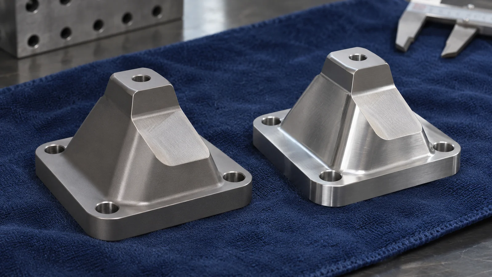
Account for finishing at contact faces and threaded interfaces. Surface processing can affect dimensions or contact behavior. The drawing should specify the delivered condition, protected areas, and acceptance timing. Do not apply a cosmetic treatment indiscriminately to a load-transfer interface or assume that similar appearance means similar friction, wear, or corrosion performance.
Plan milling and turning around the connection geometry
Depending on the design, a prototype may combine turned cylindrical features with milled inclined faces, threaded holes, slots, or mounting patterns. Decide which reference links these operations. A convenient chucking diameter may be useful during production, but the final report must still relate the critical geometry to the drawing’s functional references.
Consider the effect of clamping on a receiver with thin sections or a split tube connection. Holding it too aggressively can distort the condition being machined or inspected. Define support, machining allowance, and the state used for final measurement. The correct route depends on the actual geometry and material; a generic claim of multi-axis capability does not resolve these decisions.
Small corners and recessed features also affect tool access. Review permitted radii, edge breaks, and the clearance around screw entries. If a feature requires a secondary process, identify it before quotation. Jucheng can assess the proposed machined component scope against the files, while any specialized treatment, assembly validation, or structural test requires explicit project agreement.
Investigate uneven contact before modifying the screws
Consider a hypothetical interface sample that seats unevenly in its approved reference receiver. Verify revision, orientation, cleanliness, and the assembly method first. Then compare the contact-face geometry and the screw-axis locations with the drawing. Inspect for burrs or damaged edges that could prevent the intended seating condition.
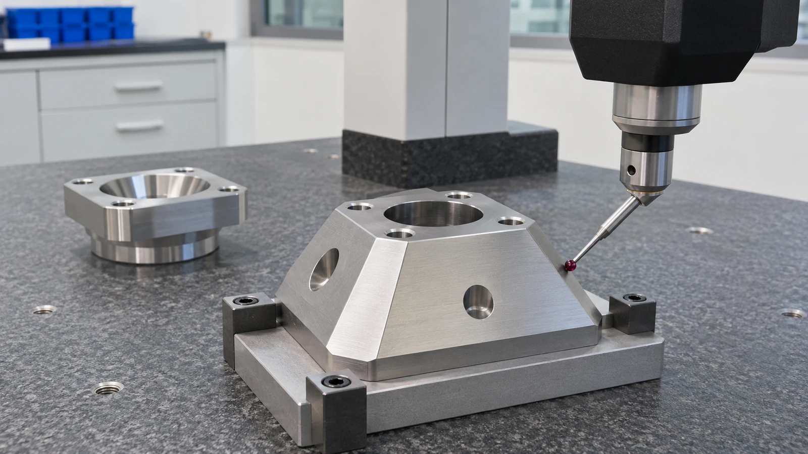
Do not assume that additional tightening is an acceptable correction. A dimensional mismatch, incorrect mating component, or wrong contact convention can remain hidden when force is increased. The design owner should assess the observation using the approved assembly requirements. Preserve the sample condition and measurement records before reworking a face or changing hardware.
This is an illustrative engineering situation, not a customer case. It highlights the difference between obtaining apparent seating and proving a controlled interface. A repeatable fixture or approved mating reference can support an assembly check, but it must have a defined purpose and cannot replace all dimensional or structural evidence.
Separate prototype acceptance from load qualification
A prosthetic pyramid adapter prototype order should include the controlled interface specification, mating references, assembly drawing, material condition, finishing, quantity, and required records. Identify critical surfaces and explain whether the samples support packaging, machining development, assembly evaluation, or an independently defined test program.
Acceptance can include profile and position measurements, thread verification, surface checks, and documented assembly observations where specified. Structural qualification and fatigue evidence belong to a separate approved plan. A material certificate, dimensional report, or resemblance to an existing catalog product does not establish a load rating. Keep the sample’s permitted use clear throughout development.
Frequently asked questions
Are prosthetic pyramid adapters universally interchangeable?
Do not assume so from appearance or category names. Establish compatibility through the controlled interface requirements, approved mating components, and required evidence for the particular system.
Does titanium automatically permit a thinner adapter?
No. Section changes affect stiffness, load transfer, contact, and processing. The responsible design team must assess and validate the revised geometry; a material substitution alone does not justify it.
Can a machined sample be assigned a catalog load rating?
No. A rating belongs to a particular validated product and its defined conditions. A custom prototype requires its own approved evidence before any equivalent claim is made.
What should be supplied before machining starts?
Provide the model and drawing, approved connection requirements, mating-part identity, material and finishing specification, sample purpose, and acceptance plan. Resolve undefined contact geometry and assembly references before selecting a production route.

