


A piston cooling jet must direct oil toward the target defined by the engine design, through the intended piston motion and operating conditions. A nozzle can have the correct hole diameter yet miss that target because its position, orientation, mounting stack, or outlet shape is wrong. For a prototype supplier, the first job is to turn that design intent into inspectable geometry and an agreed test boundary.
This article focuses on the nozzle, mounting features, internal passages, and manufacturing handoff. It does not prescribe a universal jet angle, pressure, or flow rate. Those values depend on the engine, oil conditions, cooling target, and validation plan. Keeping that distinction clear helps a development team order a useful prototype rather than an attractive but untestable part.
Start with the target and the moving clearance envelope
Show the nozzle in an engine assembly model or a controlled local section. Identify the intended target beneath the piston or at a cooling-gallery opening, as applicable to the design. Include the piston positions that matter to clearance and delivery. The nozzle’s physical envelope must also clear the crankshaft, connecting rod, and other moving components throughout the required motion.
Describe the target as a requirement rather than a single convenient CAD screenshot. The relevant question may be whether a stream reaches a region under stated conditions, not whether an ideal straight line crosses a point at one crank position. A manufacturing drawing should reference the approved targeting definition without pretending that geometry alone predicts every flow behavior.
Use the mounting face, locating feature, and outlet direction to express the geometric chain. If the nozzle rotates while a fastener is tightened, a free-state angle does not establish its installed direction. Clarify what prevents rotation and which assembled condition governs inspection. The design authority should resolve the orientation requirement before the supplier chooses a fixture.
Small outlet features deserve their own process discussion
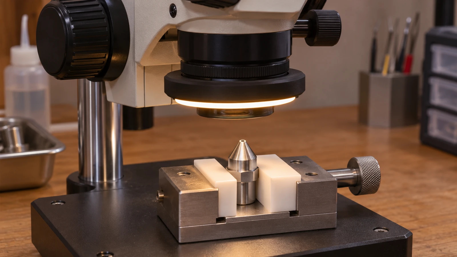
Outlet diameter, length, edge condition, and nearby internal geometry can influence the emerging stream. These features may be made by drilling or another approved process, depending on the material and geometry. Do not select a process only because its nominal hole-making capability looks adequate. Access, burr removal, and a practical method of checking the result also matter.
A drawing note that says only “deburr” leaves too much freedom near a small outlet. A remaining burr can obstruct the passage, while uncontrolled edge rounding can change the outlet geometry. Define the critical edge condition and agree how it will be verified. For a hidden intersection, decide whether inspection is possible before the passage is enclosed or connected to another component.
Separate passage cleanliness from surface appearance. A clean-looking external nozzle can contain chips or particles in an intersecting bore. The purchase specification should define the cleanliness evidence needed for the prototype and its intended test. Visual inspection, flushing records, or particle assessment answer different questions; none should be promised without confirming an actual procedure and acceptance limit.
Separate the mounting body from the formed tube
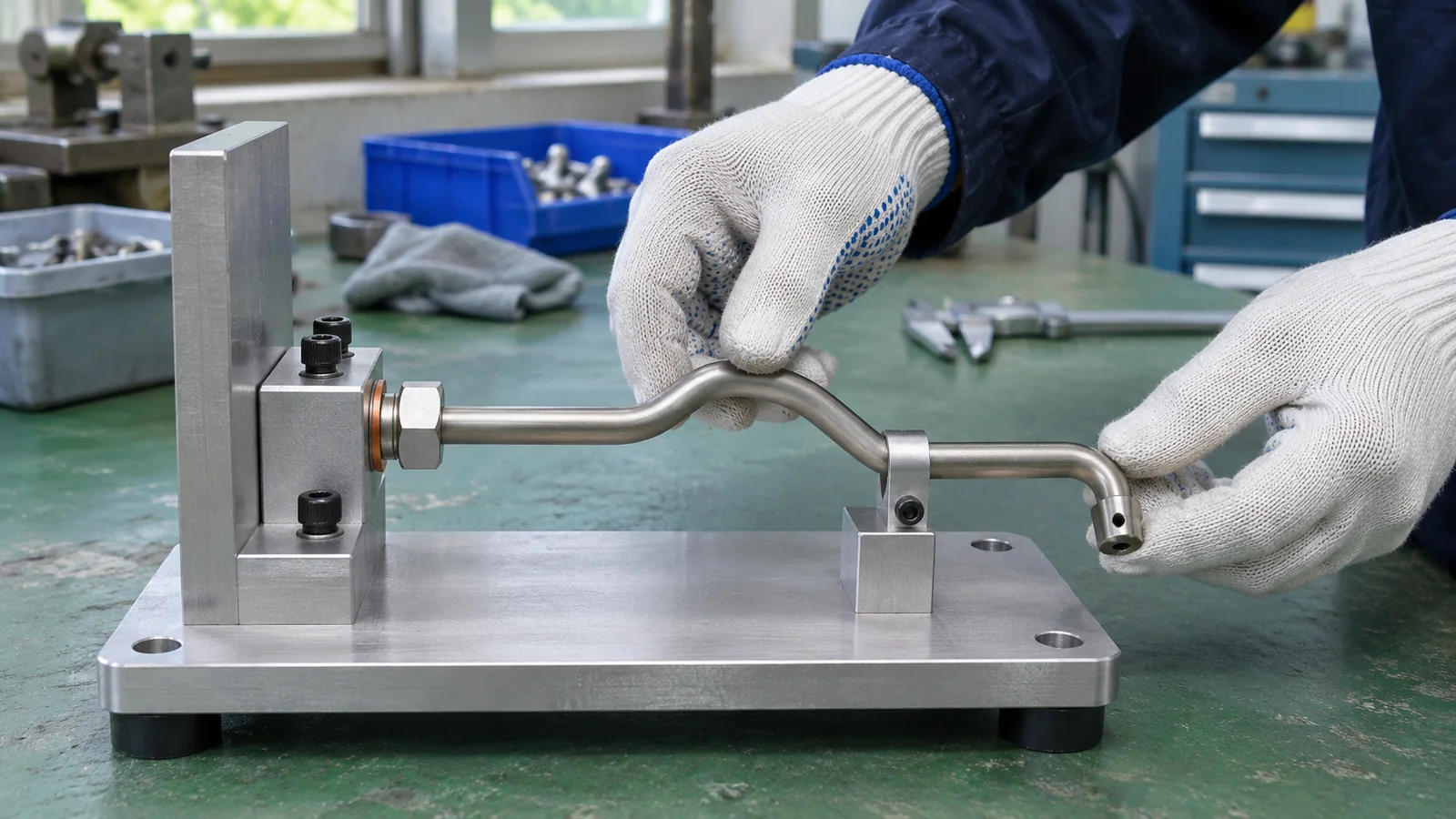
Some designs use a machined body connected to a shaped tube; others integrate the fluid path differently. The manufacturing plan should reflect the actual design rather than assume a universal construction. Identify which component establishes the installed position and which operation establishes the final outlet direction. A bend or joining operation can alter a direction that was correct earlier.
For a tube-based nozzle, check the bend envelope, unsupported length, joining interface, and clearance to neighboring parts. If the tube is formed after a machining operation, define how the assembly is located during forming. If joining adds heat, consider whether position must be verified afterward. The permitted process and any rework must follow the approved design requirements.
For a machined mounting body, communicate sealing faces, fastening features, oil-feed connections, and any orientation stop. Avoid combining a cosmetic surface requirement with a functional sealing requirement in one vague finish note. A supplier needs to know where tool marks, edge breaks, and processing allowances matter to the interface.
A drawing inspection and a spray test answer different questions
A dimensional report can establish the outlet’s geometric direction relative to mounting references. It can also record passage dimensions and connection geometry. It cannot, by itself, demonstrate that the oil stream reaches the target under operating conditions. That requires a defined test or validated analysis with inputs relevant to the particular design.
A useful spray-test request identifies the fluid, temperature or conditioning state, supply conditions, fixture orientation, measurement location, and acceptance criterion. If a valve is present, its opening behavior introduces another requirement. Do not borrow a pressure threshold from a different engine or treat a room-temperature demonstration as proof across the operating range.
Some published piston cooling jet designs include pressure-responsive components or multiple passages. The piston cooling jet patent US11674431B2 illustrates why the external nozzle shape alone may not describe the full assembly. It is an example of one design, not a manufacturing standard or permission to copy protected features.
Diagnose a missed target before changing the hole
Imagine a hypothetical prototype test in which the stream falls outside the intended target. First confirm the nozzle revision, fixture location, mounting orientation, and supply conditions. Compare the measured outlet geometry with the drawing. This sequence separates a misplaced nozzle from a flow response that differs from the design assumption.
Next inspect the passage and outlet condition. Check for a burr, contamination, damage, or an unintended edge shape. Document the as-received state before cleaning or modifying the sample; otherwise the cause can disappear without a useful record. If geometry matches but delivery remains wrong, the design team should review the flow assumptions and acceptance method.
This scenario is illustrative and does not describe a Jucheng test or customer project. Its purpose is to prevent a common development mistake: enlarging an outlet to improve apparent delivery without assessing the effect on flow demand, supply conditions, or the rest of the lubrication system. Changes belong in a controlled engineering review.
Order the prototype around a defined learning objective
An early sample might check packaging and orientation; a later sample might support an agreed flow test. Specify the objective, sample quantity, material condition, assembly state, critical geometry, and records needed. A packaging model can be useful without representing a production-ready fluid component, provided that limitation stays explicit.
For a piston cooling jet development package, Jucheng can review the proposed machined component scope against the files. Discuss small passages, access for deburring, mounting features, and required inspection before the route is agreed. Any tube forming, joining, cleaning validation, or fluid testing requires separate scope confirmation.
Frequently asked questions
Is there one correct angle for every piston cooling jet?
No. The target, engine layout, piston travel, nozzle position, and fluid behavior are design-specific. Use the engine’s approved requirements and test conditions rather than a general angle copied from another nozzle.
Does a correct outlet diameter guarantee the required spray?
No. Outlet shape, internal passage condition, installed direction, and supply conditions also matter. Geometry inspection and a defined delivery test provide different evidence.
Can a prototype use a different material from the final design?
Sometimes, for a limited and documented learning objective. A substitute can change forming behavior, stiffness, joining, and thermal response. It should not be used to infer production performance without an appropriate assessment.
What should be checked after assembly?
Confirm the mounting references, outlet direction, connection condition, and clearance envelope in the defined state. Add the agreed fluid test when the prototype’s purpose includes delivery performance, rather than assuming the dimensional report covers it.

