


A propeller guard is often described as a ring around a rotor, but the part is doing several jobs at once. It must maintain clearance from the blade, attach to the airframe, survive handling, and avoid adding more mass or drag than the application can accept. If it flexes into the propeller, the guard can create the contact it was meant to prevent. If it is too bulky, it may interfere with airflow, payload access, folding arms, or transport cases.
That is why drone propeller guard manufacturing should begin with the rotor envelope and mounting conditions. The guard geometry is tied to blade diameter, tip clearance, motor position, arm stiffness, and the intended operating environment. This component-level view fits within the broader custom drone and UAV parts manufacturing scope, but its design and validation remain specific to the aircraft configuration.
Protect the blade envelope first
The propeller envelope is not simply the blade’s static outline. Account for blade flex, rotor runout, assembly variation, vibration, and the relative movement of the arm or motor mount. Establish the minimum functional clearance from the approved aircraft design or test plan. A guard designed around a nominal CAD blade may not preserve clearance under the conditions that matter in operation.
Check the full rotation and the installation path. A removable guard may need to clear the blade during assembly, while a permanent guard may need to be installed before a folding arm is attached. Include fastener heads, motor wires, cooling openings, and the tool envelope in the CAD review. Small protrusions can make the guard difficult to remove or create a snag point for cables.
Do not make the guard so close-fitting that a minor impact or a bent mounting ear pushes it into the rotor. Also avoid assuming a large gap is harmless: it can change the protective function and may fail the program’s safety or performance requirement. The target clearance must be set and verified for the real aircraft assembly.
Follow the load from impact point to airframe
When the guard is bumped, the load travels through its hoop or ribs, into mounting tabs, and finally into the arm or frame. A thick ring does not guarantee a robust assembly if the tabs are thin or the fastener pattern puts the load through a weak local wall. Review the complete path and the condition of the mating airframe feature. The guard and its attachment should be engineered as a pair.
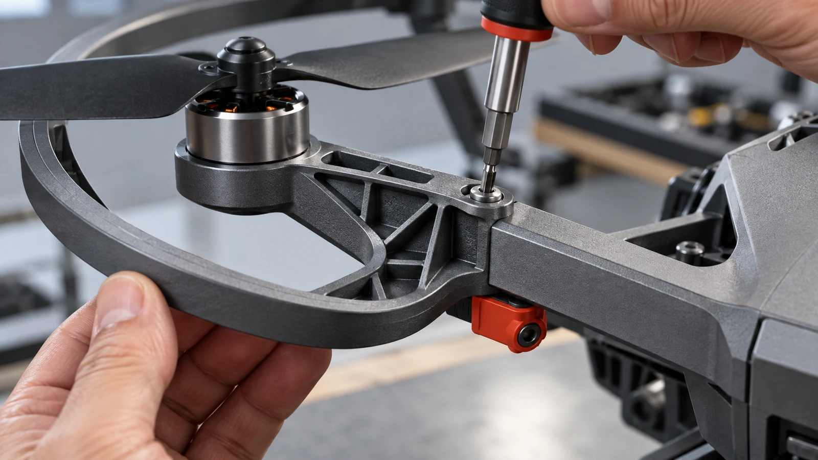
A local rib can resist bending but create a stress concentration where it joins the ring. A generous transition may improve load distribution, while a smooth but unsupported arc may flex too easily. The right geometry depends on the material, process, expected contact, and acceptable deflection. Use finite-element analysis or physical testing only with the correct boundary conditions; neither a decorative CAD rendering nor a material datasheet alone predicts the installed response.
Mounting methods also change the service task. Screws can offer positive retention but add hardware and assembly time. Clips may permit quick replacement but require an intentional release feature and enough material around the clip root. A strap or clamp may be adjustable but can shift if the interface is not designed for it. Choose the retention concept based on how the aircraft will be assembled, inspected, and maintained.
Choose geometry with airflow and access in mind
A full circular hoop, partial arc, cage, or multi-rib structure each presents different trade-offs. More coverage may increase protection in selected directions but can obstruct airflow or payload fields of view. A partial guard can reduce material but may leave an exposed contact path. Openings should be assessed against the blade sweep and the approach directions identified by the program, not selected solely for appearance.
Consider transport and field repair. A guard that protrudes beyond the arm may snag in a case or be damaged during handling. A modular design can make a damaged segment replaceable, but introduces joints and hardware that need their own inspection. If the UAV uses folding arms, confirm that the guard does not collide with the body or a neighboring propeller when folded.
Airflow is a system consideration. A guard can disturb the local flow around the propeller or motor, but the impact depends on geometry and operating condition. If flight efficiency, acoustic behavior, or control response is critical, test the actual assembly. Do not infer a performance gain or loss from guard area alone.
Prototype the risky features before tooling
A quick prototype is useful for checking rotor clearance, arm interference, hand access, storage, and latch operation. Additive manufacturing can make complex ribs and clips quickly, while CNC machining can test a metal attachment or precise mounting interface. For designs that will move to molded polymer, the prototype should identify what it proves: packaging, user handling, or initial stiffness. It does not automatically establish production material behavior or impact performance.
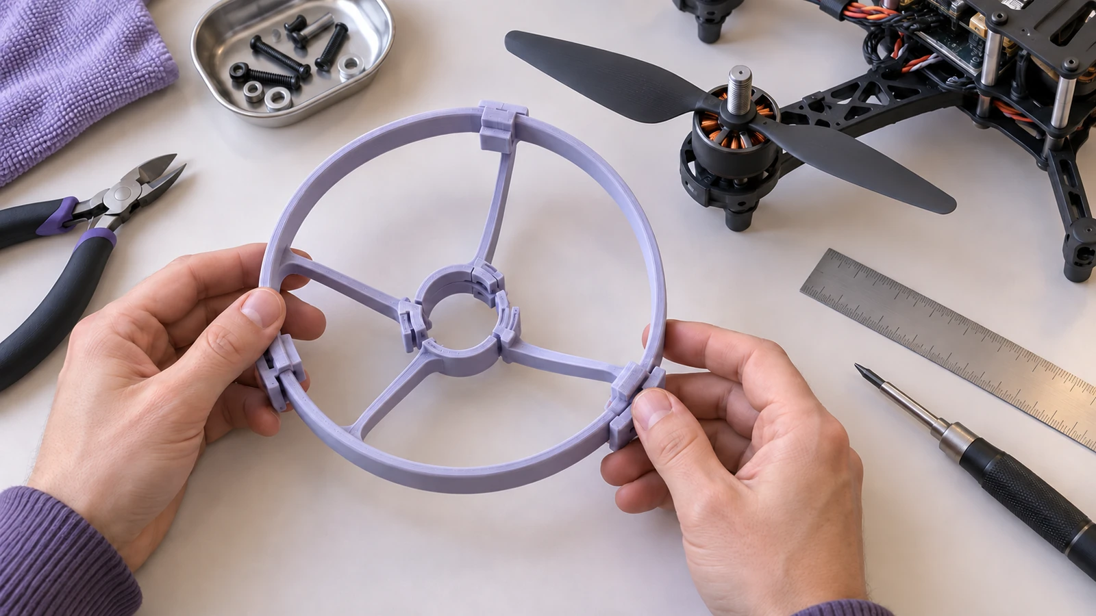
If the design is expected to use injection molding, consider draft, wall uniformity, gate position, parting line, ejector access, and the way ribs meet the outer wall. A guard with long, thin arcs can warp or vary in stiffness depending on geometry and process. A manufacturing review before tool design can identify where the part should split, how it will be supported during cooling, and which surfaces need cosmetic control.
The site supports 3D printing for prototype evaluation e low-volume injection molding for appropriate designs. These are possible routes, not a promise that every guard geometry is suitable for either process. Evaluate the drawing, expected quantity, mechanical requirements, and test scope before choosing.
Select a material for the actual failure mode
A polymer guard may need impact tolerance, stiffness, UV or weather exposure resistance, dimensional stability, or a balance of these properties. Nylon can be considered for some robust structures, but moisture conditioning and process direction may affect dimensions and behavior. Polycarbonate may be considered where impact behavior is important, but part geometry, grade, and molding conditions still matter. No generic resin label proves suitability for a particular drone or safety function.
A metal guard or attachment may suit a different use case, especially where a rigid bracket is integrated with a frame. Aluminum can provide a light structural element; a different alloy or finish may be selected according to load, corrosion, and wear requirements. Avoid adding metal mass to a rotating assembly without reviewing the aircraft-level effect and balance requirements.
For initial material discussion, Jucheng’s nylon machining information e polycarbonate material page provide process context. Final material selection should specify grade, process, finish, operating conditions, and test evidence required by the UAV design authority.
Define checks for fit and retention
Dimensional checks should cover the rotor clearance, mounting pattern, critical wall or rib sections, latch features, and any datum that aligns the guard to the motor or arm. If the part is flexible, the measurement setup must define whether the guard is free, restrained, or installed. Otherwise two inspectors may measure different shapes and report apparently conflicting results.
A functional fit check should use the intended motor, propeller, frame, fasteners, and installation sequence. Confirm that the guard can be assembled without forcing the arm, the blade maintains the specified clearance, and service access is possible. If impact or vibration validation is required, define the mounting, direction, and acceptance criteria before the test; a simple hand flex is not a substitute for a controlled protocol.
Track revisions across the guard, propeller, motor, and frame. A blade change can invalidate a previous clearance check even if the guard drawing remains unchanged. Record the approved combination and identify the configuration at inspection so replacement parts do not get mixed across airframes.
What to send with a guard RFQ
Send the guard model, drawing, mating frame and motor geometry, propeller envelope, material, finish, quantity, revision, hardware, and any defined clearance or validation requirements. Include whether the part is a prototype, a pilot build, or a repeat order. State whether the supplier is quoting only the guard or also its attachment hardware.
Ask the supplier to review thin ribs, clip roots, moldability or tool access, parting line, mounting-tab strength, and inspection setup. If a protection or flight-performance target is still under development, label it as open rather than implying it has already been verified. Clear scope keeps manufacturing feedback useful and prevents the drawing from promising a performance result that has not been tested.
A dependable propeller guard is a designed interface among rotor clearance, attachment strength, material behavior, and service. Build the part around the actual UAV configuration, then use prototype and inspection evidence to refine it before repeat production.

