


An aircraft rudder pedal assembly brings together pedals, pivot arms, cross-shafts, adjustment hardware, linkage interfaces, and floor or support structure. Its quality is experienced as controlled movement, but the manufacturing definition must address the interfaces that make that movement repeatable: pivot axes, pedal spacing, adjustment locks, clearances, and installation order.
The aircraft design authority owns the control-system travel, loads, ergonomics, and rigging limits. Manufacturing should preserve the released geometry and finish state, not infer the required pedal feel from a visual model. This guide focuses on design-for-manufacturing and inspection questions that help prevent binding, uneven adjustment, or access problems.
Contents
- Understand the assembly architecture
- Trace motion through the pedal system
- Control pivot alignment and bearing fits
- Make adjustment repeatable and lockable
- Design parts for their manufacturing route
- Inspect movement in the assembled state
Understand the assembly architecture
Identify the pedal faces, arms, cross-shaft, bearings or bushings, adjustment features, stops, and linkage connection. Determine which parts move together and which are fixed to the aircraft structure. A clear assembly drawing should show the neutral configuration and reference the approved travel and rigging documents.
Check whether the pedals adjust for reach, fold for access, or share a cross-shaft. Each feature adds interfaces and potential play. Identify the adjustment positions and the means of locking them. If left and right sides must remain synchronized, define how that relationship is established and checked.
Include covers, floor panels, wiring, and nearby structure in the review. A pedal may clear in a simplified model yet contact a panel at a travel limit or block access to an adjacent control. The aerospace manufacturing overview is general background; the aircraft’s approved assembly definition controls exact fit and function.
Trace motion through the pedal system
Follow the input from the pedal face through its arm and pivot to the connected linkage. Look for changes in direction, leverage, and motion over the full travel. A dimensional change to a pedal arm or pivot location can affect the control-system response even when the pedal still appears to move freely.
Review the assembly at both travel limits and through intermediate positions. Check for interference between pedal faces, stops, floor structure, linkage rods, fasteners, and adjustment hardware. Include expected installation variation and any defined service or maintenance position.
Do not equate a smooth manual sweep with correct control behavior. Friction, free play, stop position, and rigging are controlled by the system design and verification procedure. Manufacturing can make the interfaces consistent, but the aircraft authority defines the acceptance criteria.
Control pivot alignment and bearing fits
Pivot alignment affects friction, wear, and side loading. Establish a datum scheme that relates bearing bores, shaft shoulders, pedal-arm planes, and mounting features. If several bores share a shaft, define their coaxiality or positional relationship according to the functional design rather than measuring each independently.
Clarify whether a bushing is installed before or after finish. Press fits, coatings, and post-machining operations can alter the final bore. Specify the condition in which the bore is accepted and how it is measured. If lubrication or a dry bearing is required, follow the approved material and maintenance instructions.
Ensure that bearing retention and axial location are clear. A shaft that can migrate may change pedal spacing or contact neighboring parts. Retainers should be accessible for installation and inspection, and the assembly drawing should show their orientation.
Make adjustment repeatable and lockable
Reach adjustment may use a sliding track, threaded link, detent, or a series of indexed positions. The design should make each permitted position identifiable and ensure that the locking feature engages as intended. Avoid relying on friction alone unless the approved design explicitly uses it and defines how it is verified.
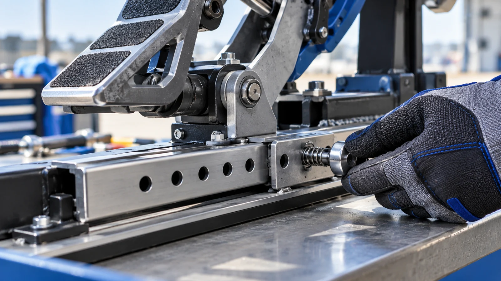
Check that the adjustment mechanism can be operated in the installed aircraft configuration. Fasteners, knobs, and locking pins need tool or hand access. A range that exists in the part model may be unusable once a floor panel or adjacent equipment is installed.
Define the procedure for setting and recording the position. If the adjustment changes linkage length or pedal geometry, the rigging process may need to be repeated. Make the required relationship visible in the assembly documentation rather than leaving it to a mechanic’s subjective judgment.
Design parts for their manufacturing route
An assembly may combine machined pedal arms, turned shafts, formed covers, and commercial bearings. Each process introduces different controls. CNC-machined arms may need stable workholding around thin webs and pivot bores. Formed covers need bend geometry and clearance. Shafts require control of bearing seats and shoulders.
Plan how mating datums are produced and inspected. If a shaft seat and cross-hole are made in separate setups, the process must retain their relationship. If a pedal face is welded or bonded to an arm, the joining route and distortion controls need approval and documentation.
For precision parts, the CNC machining capability can be reviewed against the released geometry and material. A prototype assembly can help find access and interference issues, but the production and flight configuration must follow the approved qualification and quality plan.
Inspect movement in the assembled state
Component inspection should verify bearing seats, pivot axes, spacing, stops, adjustment features, and attachment datums. Assembly inspection then checks free movement, permitted travel, left-right relationship, locking engagement, clearances, and rigging according to the controlled procedure.
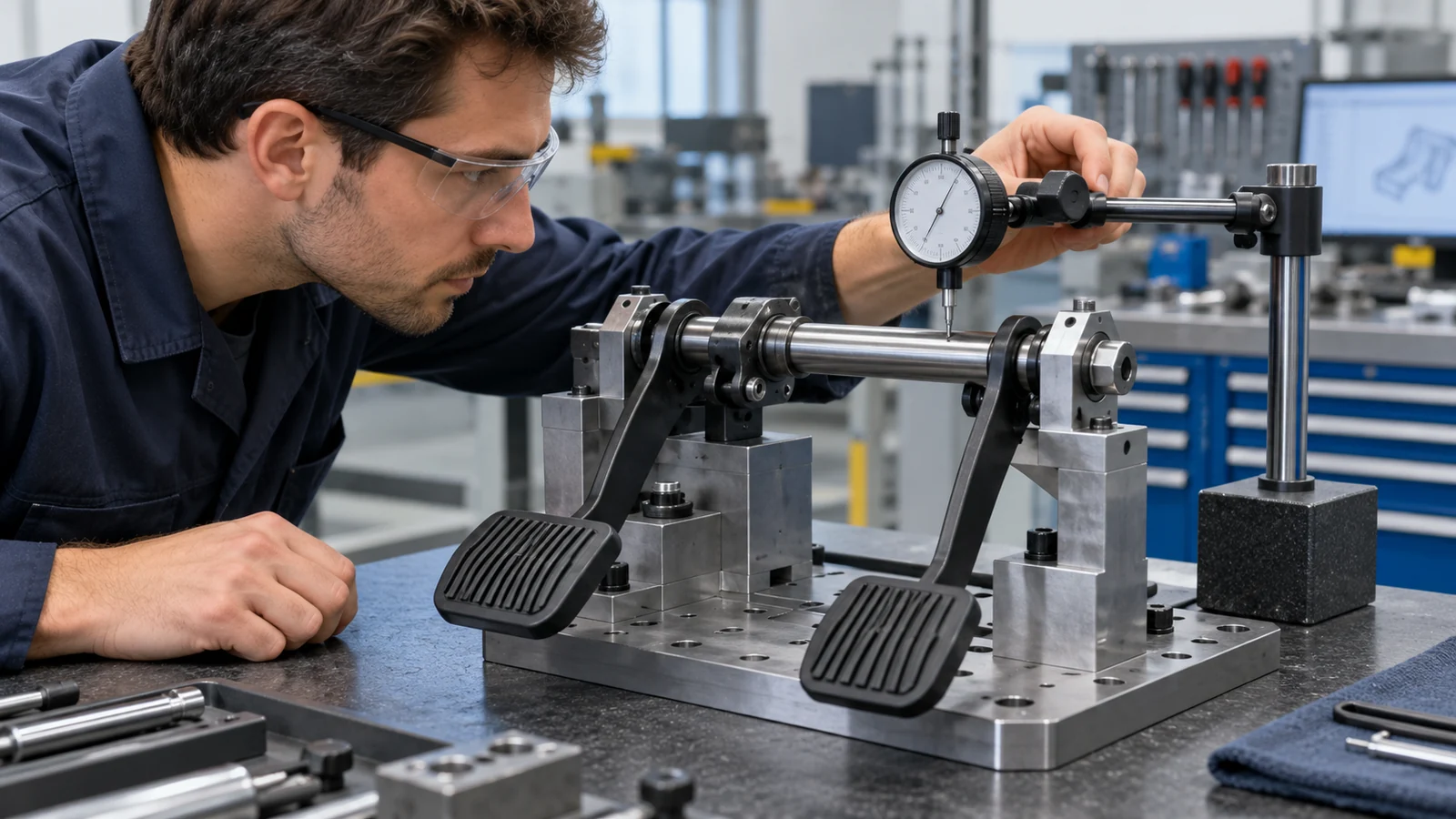
Define how pedal force or friction is measured if those characteristics are controlled. Use the required fixture, direction, travel range, and acceptance limits. A technician’s subjective feel may supplement a check but should not replace a specified measurement.
Record part and assembly revisions, bearing or bushing configuration, adjustment position, and any approved deviations. If an adjustment is made after inspection, identify which checks must be repeated. This preserves traceability from the machined interfaces to the completed assembly.
Reliable pedal movement starts with defined interfaces
An aircraft rudder pedal assembly is easier to manufacture and inspect when the design clearly controls motion, pivots, adjustment, stops, and access. The assembly should be reviewed as a connected mechanism, not as a collection of individually acceptable parts. That approach helps engineering, manufacturing, and maintenance teams work from the same configuration and acceptance basis.
Use an integration check to catch assembly-stage friction
Before completing the assembly, confirm that the inspection setup represents the installed supports and the intended pedal orientation. Check that the pivot hardware is seated, adjustment locks are engaged, and the connecting link is installed in the approved position. Move the assembly through the defined travel while observing clearances at the floor, stops, and adjacent structure. Record any contact or drag rather than resolving it by bending a bracket or changing a stop without authorization.
If the assembly includes adjustable pedals, repeat the movement and locking check at each permitted position. Verify that the adjustment feature can be operated with the surrounding panels installed and that the final setting can be identified during later inspection. A documented sequence makes it easier to compare builds and investigate a change in feel after maintenance.

