


A satellite reaction wheel is a rotating actuator that changes spacecraft orientation by exchanging angular momentum with the spacecraft body. The wheel’s function depends on the complete assembly—rotor, bearings, motor, housing, mounting interfaces, electronics, and control system—not on a machined disk alone. Manufacturing quality therefore has two layers: each component must match its released drawing, and the integrated wheel must meet the system-level balance, vibration, thermal, and operational requirements defined by the spacecraft program.
That distinction matters during sourcing. A precision-machined rotor or housing can be an important part of a development program, but machining inspection is not the same as dynamic balancing, environmental qualification, or flight acceptance. Buyers should define which component is being procured, which interfaces the supplier controls, and which tests belong to the wheel integrator or spacecraft authority.
Contents
- Understand the wheel as part of an attitude-control system
- Separate component accuracy from assembly balance
- Define the rotor and housing interfaces
- Choose a process route from geometry and quantity
- Treat material and surface requirements as controlled inputs
- Make inspection useful to the integrator
- Build a supplier package that protects the test plan
- FAQ
Understand the wheel as part of an attitude-control system
When a reaction wheel speeds up or slows down, the spacecraft body responds in the opposite direction to conserve angular momentum. NASA’s SmallSat Institute describes wheel selection in relation to spacecraft inertia, required momentum storage, and maneuver needs. It also notes that wheel imbalance and construction issues can disturb pointing stability. These system effects explain why the manufacturing discussion must connect part geometry with the integrator’s requirements rather than treating “high precision” as a sufficient specification.
The mechanical parts may include a rotor or flywheel, shaft features, bearing seats, a motor interface, a housing, and mounting faces. Not every design uses the same architecture. The supplier should work from a controlled part definition and should not infer a complete reaction-wheel design from a reference image or a generic CAD model.
For broader project context, Jucheng’s Aviation & Aerospace page describes aerospace prototyping and parts manufacturing. It does not establish that a particular part is flight-qualified or that the site supplies a complete spacecraft actuator; those boundaries must remain explicit in the RFQ.
Separate component accuracy from assembly balance
Dimensional accuracy and balance are related but not interchangeable. A rotor may meet its diameter, bore, and face-runout requirements while the assembled rotating group still has residual imbalance. Conversely, a balance correction cannot compensate for an incorrectly located mounting interface or a misaligned bearing seat. The drawing, process plan, and test plan should assign each requirement to the operation capable of verifying it.
At component level, the engineering team may control concentricity between the shaft axis and rotor features, face runout, bearing-seat geometry, mass properties, and attachment patterns. At assembly level, the integrator may specify static or dynamic balancing conditions, speed ranges, correction planes, test fixtures, and acceptance thresholds. Those values should never be invented by the machine shop or copied from a different wheel design.
NASA’s SmallSat technology review explains that static and dynamic imbalance can introduce forces and moments that disturb spacecraft attitude. That makes the source and condition of any balance requirement essential: the purchase document should state whether the supplier is machining an unbalanced blank, preparing a balanced subassembly, or delivering a complete tested wheel. If balancing is outside the machining scope, the handoff should preserve the datums and records the balancing provider needs.
Define the rotor and housing interfaces
The most consequential features are often interfaces between components: a shaft bore and bearing seat, a rotor face and spacer, a housing pilot and mounting surface, or fastener locations that establish alignment in the spacecraft bus. Each interface should have a defined reference frame and a measurement strategy.
\n
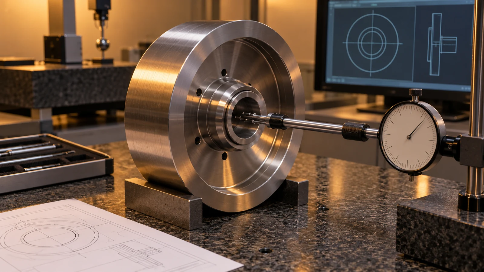
Before quoting, ask:
- Which axis is the primary datum for the rotating group?
- Which surfaces locate the bearings, motor, and housing relative to that axis?
- Which faces control axial position or preload through the assembly stack?
- Which fastener pattern, dowel, or pilot feature controls installation orientation?
- Which characteristics must be measured before assembly makes them inaccessible?
These questions help avoid a drawing package where each component is individually dimensioned but the accumulated stack is not meaningfully controlled. If a housing is machined in multiple setups, the process plan should preserve a common reference for the bearing seats and mounting face. If a rotor has thin sections or a large mass removal ratio, the design team should determine whether roughing, stress relief, and finishing stages are needed for its material and geometry; no sequence should be assumed without review.
Choose a process route from geometry and quantity
Rotationally symmetric parts may use turning or boring for primary diameters and faces, while pockets, bolt patterns, flats, and access features may need milling or drilling. Complex housings may require multiple orientations or multi-axis milling to reach features while maintaining references. The best route depends on the part envelope, material condition, wall thickness, feature accessibility, quantity, and the approved drawing.
For prototype and low-volume work, a process route may prioritize fast design iteration and accessible measurement. For repeated production, fixture repeatability and inspection planning become more important. Additive manufacturing can support non-flight fit-check parts or tooling in some development contexts, but it should not be presented as an automatic substitute for a specified metallic flight component. Material properties, post-processing, surface condition, and qualification must be separately established by the responsible engineering authority.
Jucheng’s CNC machining service page lists milling, turning, wire EDM, and grinding among its capabilities. A project review should still confirm the specific part envelope, tolerance scheme, material, inspection method, and deliverable records before a process is selected.
Treat material and surface requirements as controlled inputs
Material selection for a reaction-wheel component is a system decision. Density affects mass and inertia; stiffness and geometry influence structural response; thermal expansion can change clearances; coatings or surface treatments may affect fit, wear, corrosion protection, or cleanliness. These relationships do not identify one universally correct alloy. They explain why the design authority must specify grade, product form, condition, heat treatment, surface finish, and any coating or cleanliness requirement.
The manufacturing RFQ should identify the exact material standard and revision, required traceability, any permitted substitutions, and whether the material certificate must be linked to the part or lot. Surface requirements should distinguish functional bearing or datum surfaces from nonfunctional exterior surfaces. If a coating changes a fit or dimension, the drawing or process plan should define how that is accounted for.
Il CNC machining materials library summarizes broad materials available for machining. It is a starting point for discussion, not a substitute for the spacecraft specification, material allowables, or program-level approval.
Make inspection useful to the integrator
A supplier inspection report is most valuable when it uses the same datums and revision as the design package. For a reaction-wheel component, a useful report might address the primary axis, bearing seats, mounting faces, bolt pattern, runout, and other drawing-defined characteristics. The exact characteristics and acceptance values must come from the controlled drawing.
\n
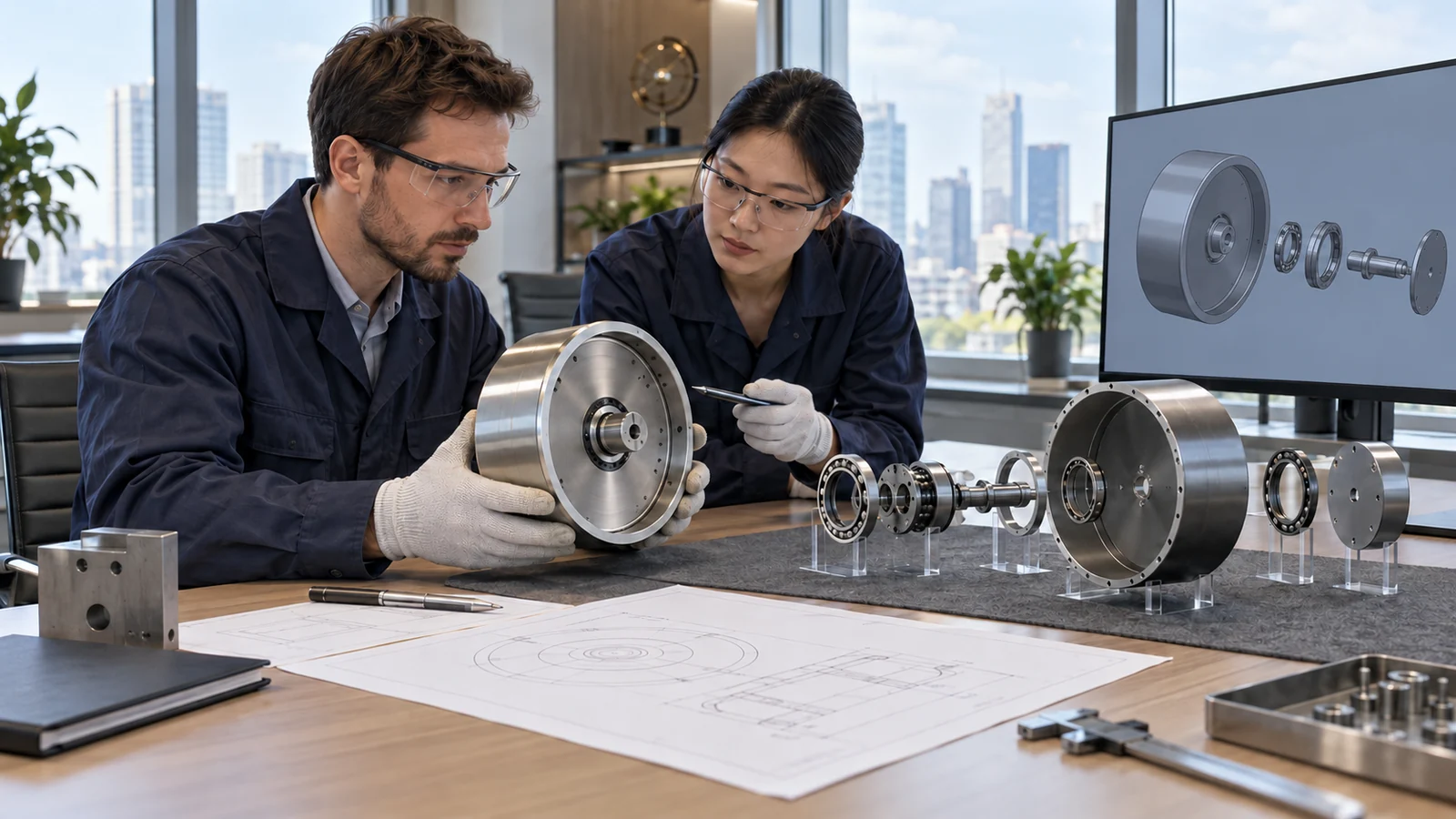
Measurement access should be planned before the part is complete. A deep bore may need a specified gauge or an agreed coordinate measurement strategy. A thin rim may require support that avoids distorting it during measurement. A feature that will be hidden after assembly should be recorded before installation. If mass properties or balance are required, state the component boundary, fixture, speed, correction planes, and acceptance process rather than writing only “balanced.”
Record identity matters as much as the measurement. Tie results to the part number, revision, serial or lot identifier, material record, and inspection equipment status where required. Jucheng’s quality assurance page lists dimensional, material, and first-article documentation examples; the purchase order should define which records apply to this specific development or production stage.
Build a supplier package that protects the test plan
A complete handoff should contain the controlled 2D drawing, 3D model, revision, quantity, material and condition, surface requirements, inspection characteristics, balance or mass-property requirements if applicable, and documentation expectations. Identify what the supplier will manufacture and what the integrator will assemble or test. Include the planned stage—engineering mock-up, fit-check hardware, development component, or production part—because acceptance evidence differs across those stages.
When asking for a quote, invite the supplier to flag features that need special fixturing, inaccessible measurement, material procurement lead time, or a clarification of balance scope. Agree on whether the supplier may propose process changes and who approves them. This is particularly important when a geometry change could alter inertia, interface stack-up, or the test configuration.
The strongest handoff is not the longest document; it is the one that prevents a supplier from guessing where component manufacturing ends and system verification begins. That clarity helps the integrator preserve control of balance, environmental tests, and flight acceptance while still receiving parts that are traceable to a released definition.
FAQ
Does a machined reaction-wheel rotor need to be balanced?
That depends on the program’s component and assembly requirements. A finished rotating assembly may require balance testing, but the specified test boundary, fixture, speed, correction planes, and limits must come from the responsible design authority.
Can dimensional inspection prove reaction-wheel pointing performance?
No. Dimensional inspection verifies specified geometry. Pointing disturbance and operational performance depend on the integrated wheel and spacecraft system, including balance, bearings, motor behavior, control electronics, mounting, and test conditions.
Is a reaction wheel the same as a gyroscope?
No. A reaction wheel is an actuator that exchanges angular momentum to change spacecraft attitude. A gyroscope is a sensing device used to measure angular motion or orientation; spacecraft architectures can use both.
What should be sent with an RFQ for a reaction-wheel component?
Send the controlled drawing and model, material and condition, revision, quantity, datum scheme, surface requirements, inspection records, and a clear statement of whether balance testing is in or out of supplier scope.
Conclusione
Satellite reaction wheel manufacturing is best managed as a chain of controlled interfaces, not a promise that one precision-machined component guarantees system performance. Define the rotor and housing datums, specify material and finish from the approved design, preserve access for inspection, and assign balance and environmental tests to the responsible party. This gives procurement a clearer scope and gives the spacecraft integrator the evidence needed to continue system-level verification.
Source note: NASA SmallSat Institute and NASA Science explain reaction-wheel momentum exchange and the role of wheel imbalance in spacecraft disturbance. This article is manufacturing-scope guidance, not spacecraft design approval or flight-qualification evidence.

