


Contents
Start with the Part Definition
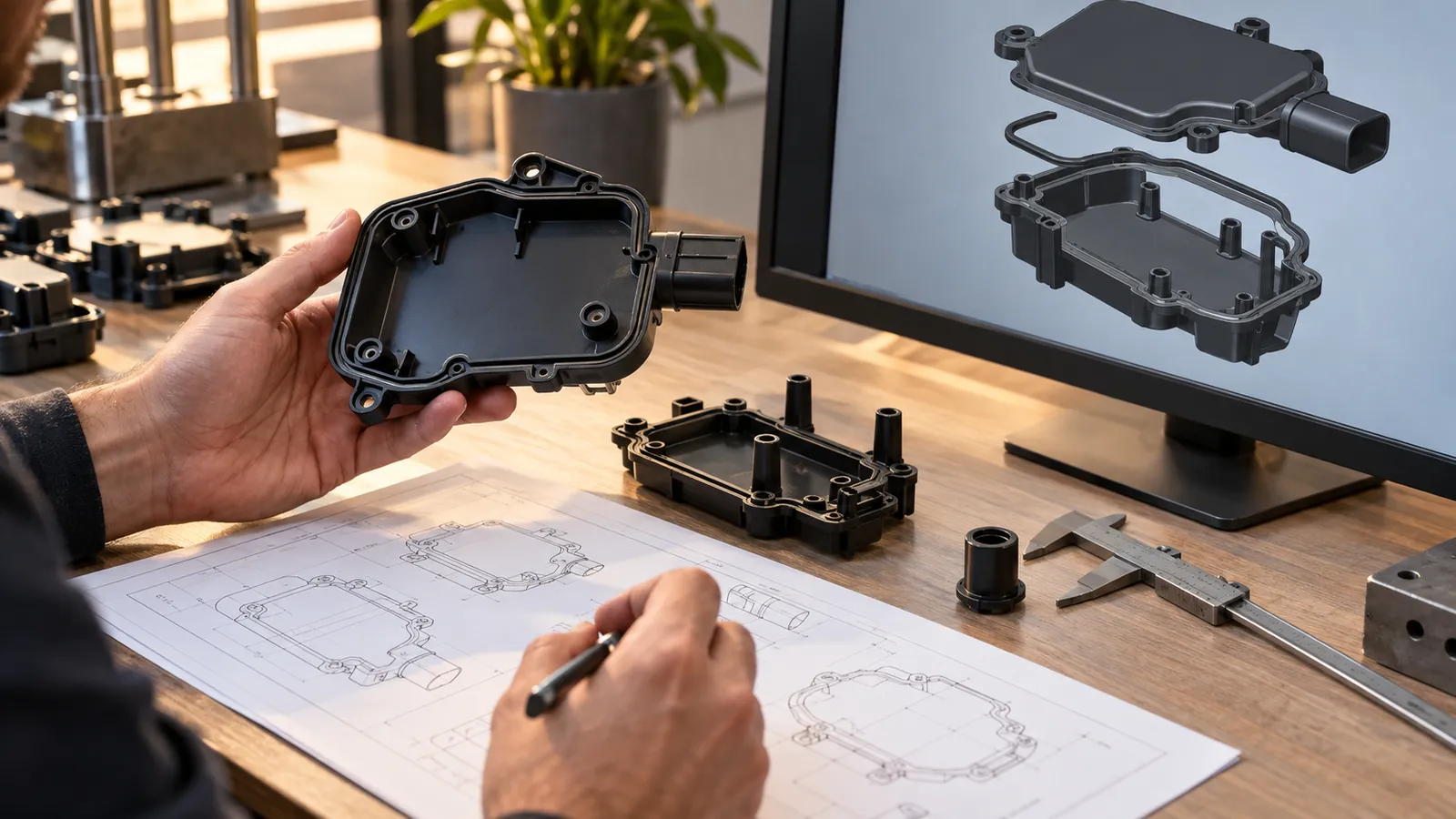
The first review should separate requirements that are truly functional from preferences that can be negotiated. A console carrier, sensor cover, battery-adjacent bracket, or interior trim component may need different evidence even when all are molded from polymer. Capture load, temperature, chemical exposure, vibration, UV exposure, assembly method, visible surfaces, and expected annual volume before deciding on tooling. A useful requirement sheet also identifies interfaces. Hole locations, snap fits, bosses, sealing lands, clips, and fastener seats often control the design more strongly than the outer styling surface. If those interfaces are not dimensioned and prioritized, the mold may produce a visually correct part that cannot be assembled. For automotive injection molding, interface control is usually more valuable than chasing a nominally perfect outside contour.
| Requisito | Why it matters | Early evidence |
|---|---|---|
| Load and vibration | Drives ribs, bosses, and resin choice | Load path review and prototype test |
| Temperature and fluids | Affects polymer stability and finish | Duty-cycle and exposure definition |
| Assembly interface | Controls tolerances and warpage risk | Datum scheme and trial fit |
| Visible surface | Sets gate, weld-line, and texture decisions | Appearance map and sample standard |
Make Geometry Work with the Mold
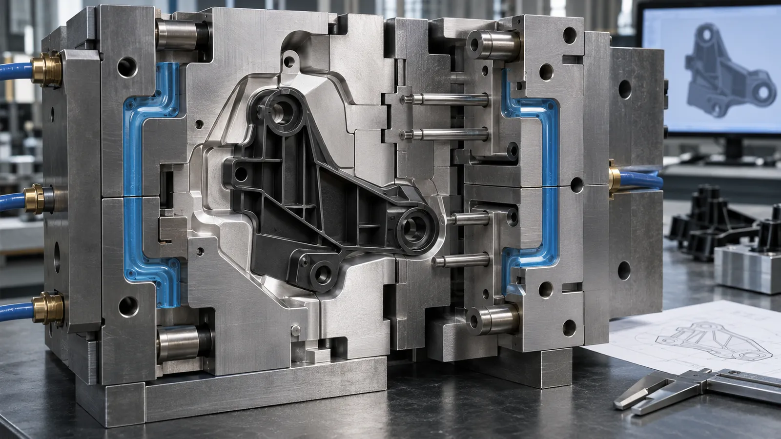
Injection molding rewards controlled thickness, predictable cooling, and clean release. Uniform walls are helpful, but uniform does not mean identical everywhere. Local thick sections around bosses or mounting points can create sink, voids, or long cooling times. The design team should transition thickness gradually, core out heavy areas, and use ribs where stiffness is needed without adding unnecessary mass. Draft is another practical negotiation. A textured surface generally needs more draft than a polished surface, and deep ribs or blind pockets may require slides, lifters, or a redesigned parting line. Every additional mold action can affect cost, maintenance, and cycle stability. A DFM review should therefore show the proposed pull direction, parting line, gate region, ejection strategy, and areas where cosmetic marks are acceptable.
- Keep ribs and bosses connected to load paths instead of scattering them for appearance alone.
- Use radii at transitions to reduce stress concentration and improve material flow.
- Reserve cosmetic surfaces for controlled gate, ejector, and weld-line locations.
- Review warpage risk around asymmetric walls, inserts, and long flat panels.
Choose Resin Around the Real Duty Cycle
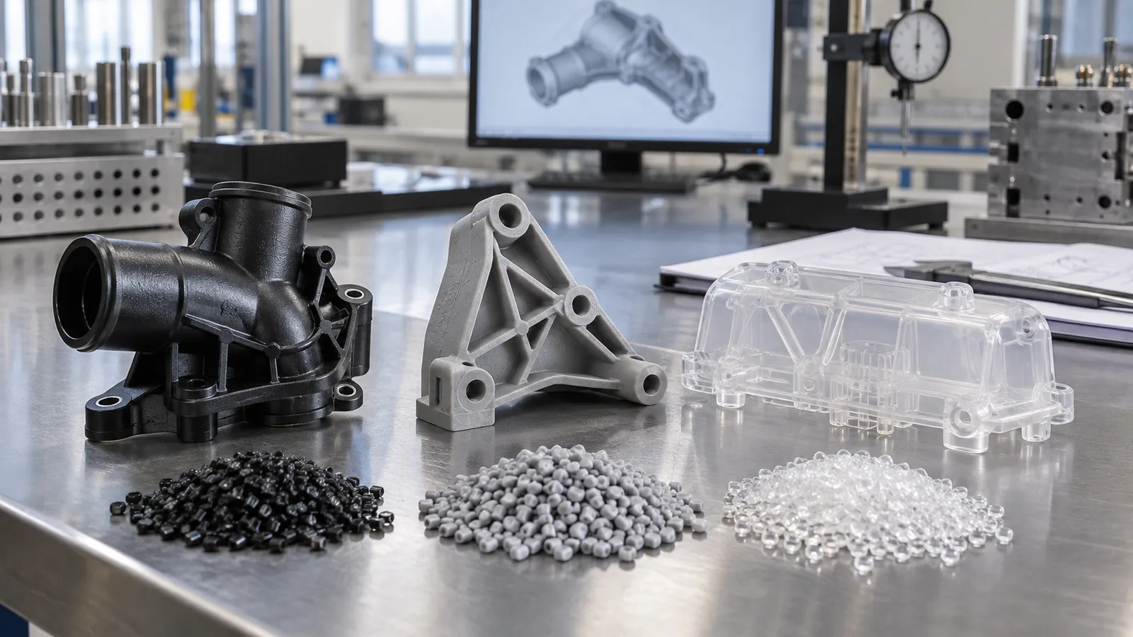
Material selection should follow the part’s job, not a generic list of automotive plastics. PP may be attractive for weight and cost, while ABS can support a different balance of appearance and impact performance. PA, PBT, PC, PC/ABS, and reinforced grades may be appropriate when heat, stiffness, dimensional stability, or electrical behavior becomes important. The correct choice depends on the environment and the interface requirements. Filled grades and flame-retardant formulations can change flow, shrinkage, weld-line strength, tool wear, and surface appearance. A resin that performs well in a flat coupon may behave differently around a thin wall, a knit line, or a glass-filled boss. Ask for the material grade, processing window, conditioning requirements, and applicable test method to be recorded with the part definition. That record is useful when a program moves from prototype quantities to recurring production.
| Material decision | Design consequence |
|---|---|
| Unfilled engineering resin | More predictable appearance and easier flow |
| Glass-filled resin | Higher stiffness but greater anisotropy and tool wear |
| Soft elastomer or TPE | Better grip and sealing, with different shrinkage behavior |
| Flame-retardant grade | May require tighter process control and appearance review |
Use Tooling to Protect Repeatability
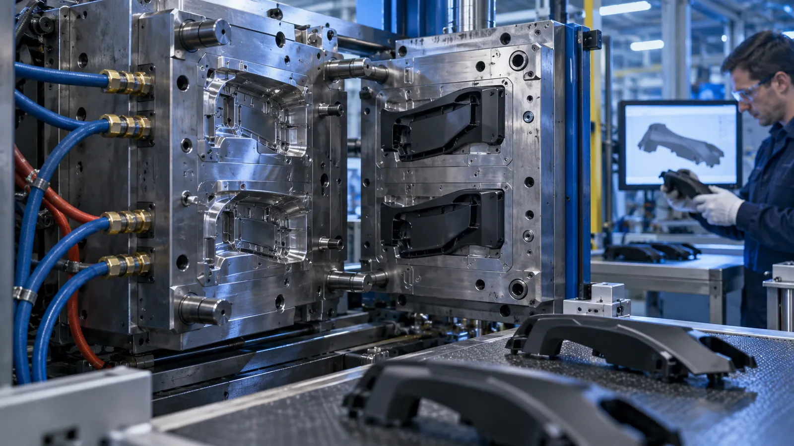
Tooling strategy should reflect the program stage. A bridge tool or soft tool may be appropriate for a pilot build when the team is still learning about fit, trim, or assembly. A hardened production mold becomes more attractive when volume, cycle life, automation, and long-term spare-part support dominate the decision. The best choice is not the cheapest mold; it is the tool that matches the uncertainty and expected demand. Gate selection, cooling layout, venting, ejection, and steel condition all influence repeatability. A well-documented mold trial should record fill behavior, short shots, sink, flash, warpage, cycle time, and dimensional results. Those observations should lead to controlled changes rather than informal polishing and repeated sampling. For complex automotive injection molded parts, a mold history is part of the quality record.
- Review mold-flow assumptions against actual gate, vent, and cooling decisions.
- Define critical-to-function dimensions before the first tool trial.
- Keep approved samples and appearance standards with the tooling record.
- Plan maintenance access for slides, lifters, inserts, and wear surfaces.
Validate Fit, Function, and Appearance
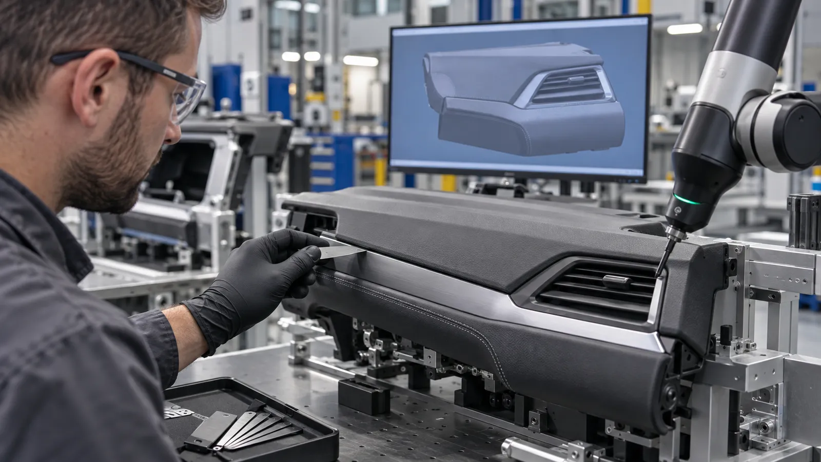
Validation should be staged. First confirm that the part can be molded consistently. Then check dimensions and interfaces. After that, test the part in the relevant assembly and environment. A panel may need appearance and gap checks; a fluid-handling component may need pressure or leak testing; a bracket may need load and vibration evidence. The inspection plan should follow failure modes, not just list every available measurement. Dimensional inspection is most useful when it is tied to datums and assembly behavior. A CMM, optical system, gauges, or functional fixtures can each be appropriate for different features. The report should show which features were measured, the method used, and the result against the agreed tolerance. This keeps prototype learning connected to the eventual production control plan.
| Validation layer | Typical question |
|---|---|
| Moldability | Can the tool fill, cool, vent, and eject consistently? |
| Dimensional fit | Do critical interfaces assemble on the intended datums? |
| Functional behavior | Does the part carry, seal, guide, protect, or locate as required? |
| Aspetto | Are texture, gloss, weld lines, and gate marks acceptable? |
What the Manufacturing Partner Should Return
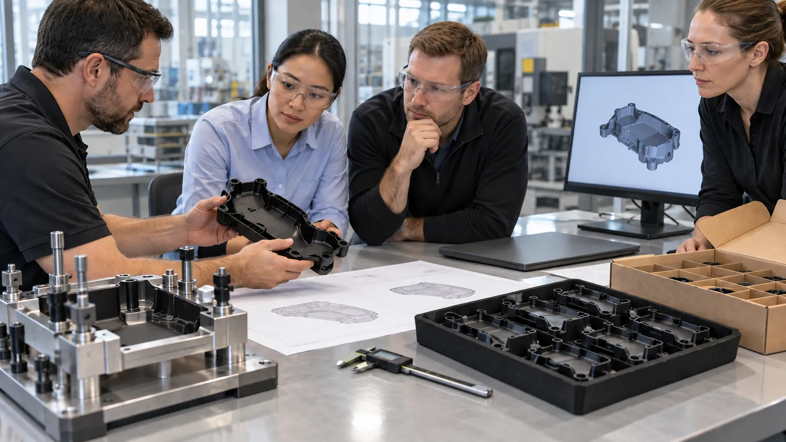
A capable manufacturing partner should return more than a price and a promised delivery date. The handoff should include DFM comments, proposed material, tooling assumptions, sample timing, inspection approach, and a clear list of open decisions. That information lets an engineering team compare suppliers on risk rather than on unit price alone. For global programs, communication discipline matters as much as equipment. Revision control, sample labeling, feedback records, and change approval prevent a late design update from being mixed with an earlier tool condition. When the supplier can support prototyping, tooling, molding, secondary finishing, inspection, and assembly coordination, the project gains a single technical thread from first sample to production release.
- A controlled drawing and revision history.
- A material and process recommendation tied to the duty cycle.
- A tooling and sampling plan with measurable acceptance criteria.
- Inspection data linked to datums and critical interfaces.
- A clear change-management path after approval.
The most reliable automotive injection molded parts come from decisions that are connected: requirements guide geometry, geometry guides tooling, tooling guides process control, and inspection proves the final interfaces. Treating those decisions as one chain is what makes a molded component ready for real automotive manufacturing program.

