


What forming changes in the part
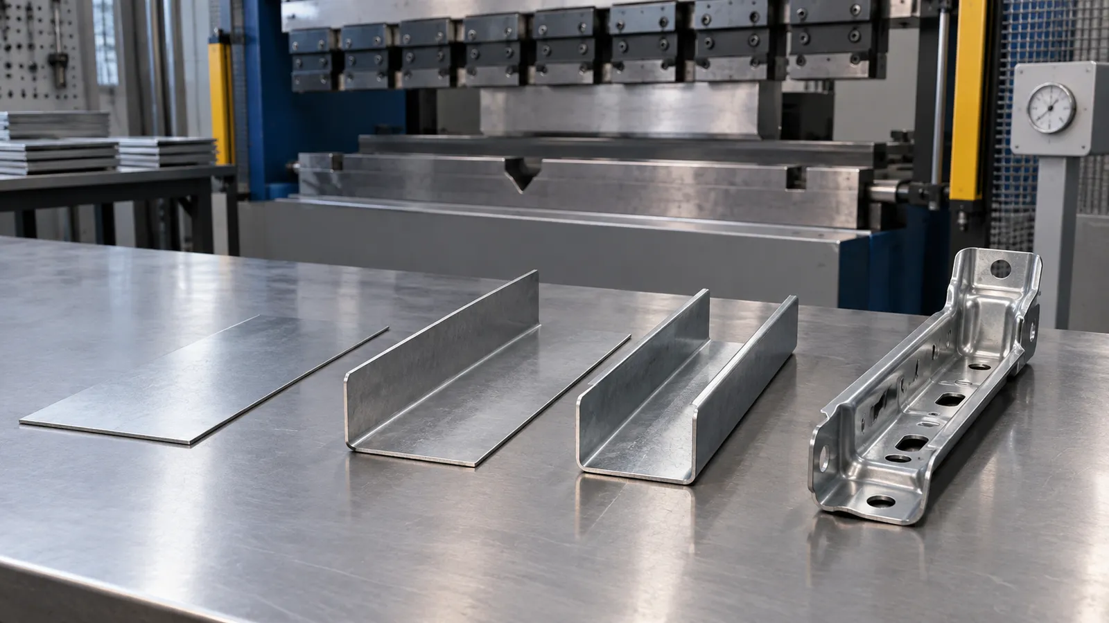
Forming does more than add an angle. It changes stiffness, load paths, clearance, edge position, and how the part locates in the vehicle. A flange can turn a flexible sheet into a stable support. A bead can increase rigidity without adding a large amount of mass. A hem can protect an exposed edge and improve assembly handling. A drawn feature can create depth, but it also introduces material flow and potential thinning.
For that reason, the manufacturing discussion should start with the job of the component. Is it carrying a sensor, shielding a hot zone, supporting an electronics module, guiding a cable, or contributing to a larger structure? A part that is visually similar to another bracket may need a different forming strategy because its load, temperature, or installation sequence is different.
When the design is still moving, fabricated prototypes give the team a quick way to test the envelope. The first sample is not merely a check of whether the blank can be bent. It is evidence about tool access, fastener reach, clearance, vibration behavior, and whether the final form is practical to manufacture repeatedly.
Bend radius is a design variable
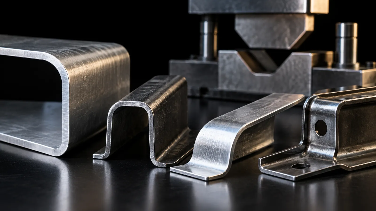
Inside radius affects cracking, springback, stiffness, appearance, and the available space around nearby features. A radius that is too tight for the chosen alloy can split during forming. A very large radius may move the flange or consume packaging space. Holes placed too close to a bend can deform or lose their intended position.
Designers should define the important radius in relation to material thickness and grade, then review the bend direction against rolling direction when the application is sensitive to cracking. Corner relief also matters. Without a suitable relief, the material can tear or bulge where two bends meet. These details are small on a CAD screen but decisive in the first formed parts.
| Caratteristica | Possible risk | Useful design response |
|---|---|---|
| Tight inside radius | Cracking or unstable form | Review radius-to-thickness relationship |
| Hole near bend | Hole distortion or shift | Move the hole or pierce in a controlled secondary operation |
| Narrow flange | Poor tool contact or weak edge | Increase flange width or change the locating strategy |
| Intersecting bends | Corner tearing or interference | Add relief and confirm bend sequence |
Springback needs a plan
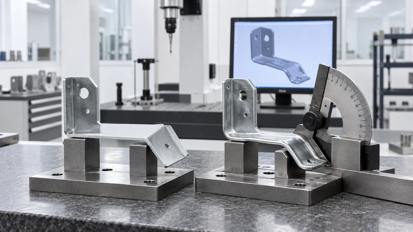
Springback occurs because the sheet retains elastic energy after the forming load is removed. Its amount depends on yield strength, thickness, radius, forming direction, tooling condition, and the shape of the feature. Two materials with the same thickness can return to different angles. A part can also change as the tool wears or the incoming material lot changes.
Compensation may be built into the tool, but compensation is more reliable when the design has already identified critical bends and datums. Do not apply the same tolerance to every angle. A bend that locates a sensor needs a different control strategy from a flange used only for clearance. The assembly should determine where the measurement effort goes.
Prototype forming also helps calibrate expectations. A low-volume sample can expose whether the digital model needs a compensation factor, whether the bracket requires an additional bead, and whether the intended fastener can be installed without forcing the part into position.
Material selection changes the window
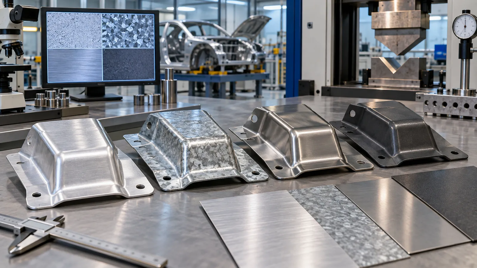
Steel, galvanized steel, stainless steel, and aluminum alloys each bring different combinations of strength, elongation, corrosion resistance, density, and surface behavior. Aluminum can support lightweighting, but it may require a different radius, forming speed, or joining approach than steel. Galvanized stock can provide corrosion protection, while the coating must be considered during forming and welding. Stainless steel may be selected for heat or chemical exposure, but its work-hardening behavior can influence the operation.
Finish is part of the design, not a final decoration. Powder coating, painting, plating, conversion coating, anodizing, and passivation can change appearance, corrosion resistance, electrical contact, and dimensional fit. Masking may be needed on grounding or sliding surfaces. If a formed edge will be visible to a vehicle occupant, deburring and cosmetic expectations should be stated separately from general dimensional requirements.
Build the operation sequence
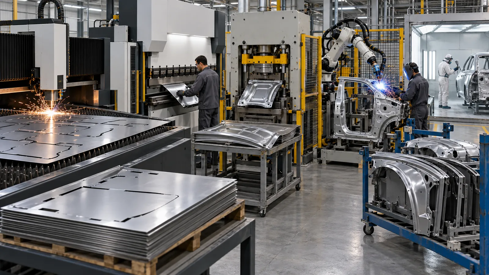
A forming route may include laser cutting, blank preparation, press-brake bending, stamping, deep drawing, piercing, embossing, deburring, welding, hardware insertion, machining, and finishing. The order determines what can be measured and how stable the final part will be. A hole made before forming may move with the bend. A hole made afterward may be more accurate but require access and an additional operation.
- Establish the datums. Identify the surfaces and holes that locate the part in the vehicle.
- Review the blank. Check grain direction, nesting, edge quality, and material utilization.
- Simulate the bend path. Confirm tool access, collision risk, flange width, and bend order.
- Form and inspect the first article. Measure the functional features before secondary operations.
- Complete joining and finish. Recheck interfaces after welding, coating, or hardware installation.
This sequence prevents the laser cut blank from becoming the only object under review. The vehicle receives a formed, finished component, so the entire route should be accountable for the result.
Assign tolerances to the interface
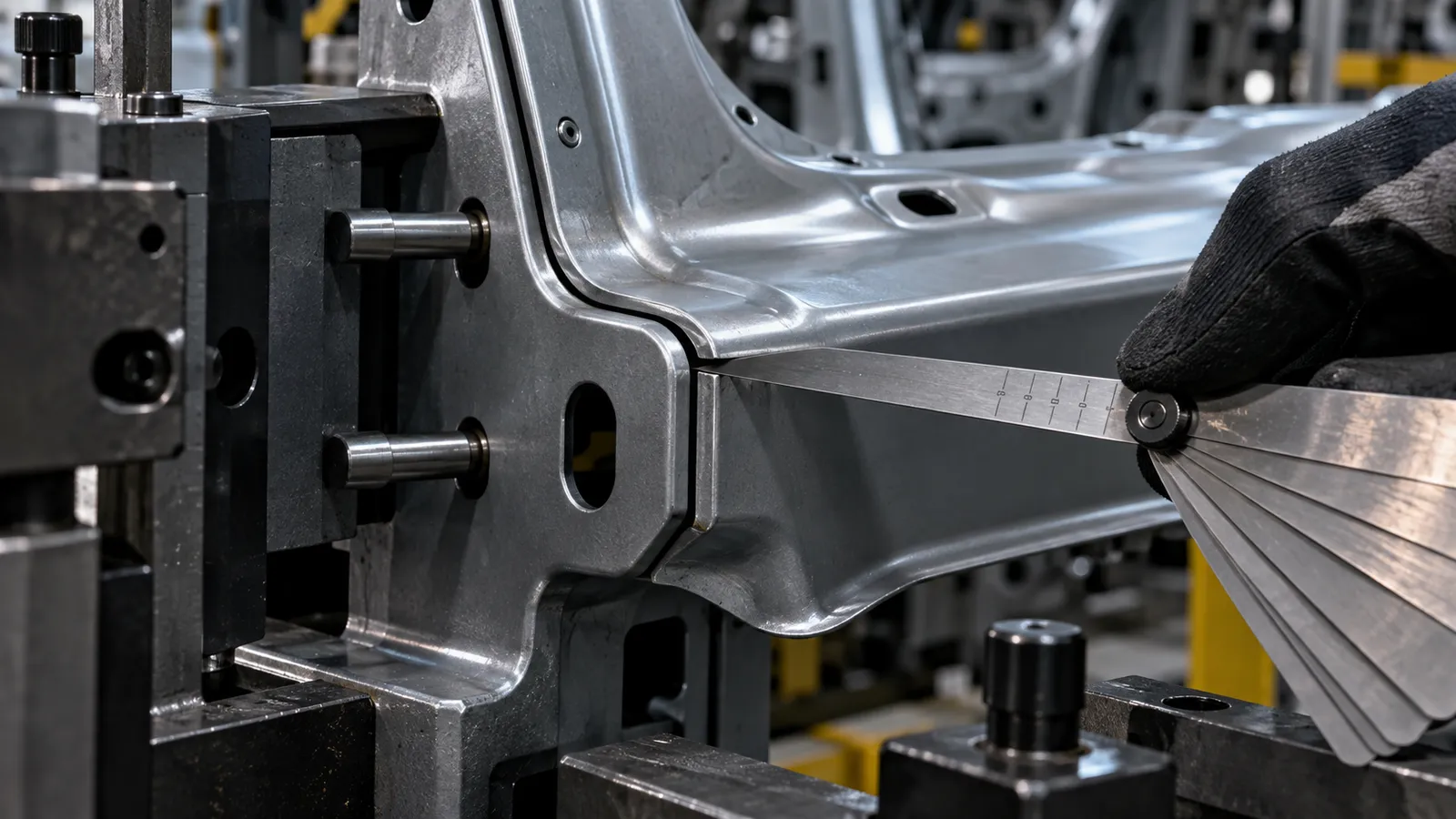
Tolerance strategy should follow function. A hole that locates a sensor, bushing, or bracket may need stronger positional control than a broad clearance opening. A flange that seals against another panel may need flatness and profile control. A hidden edge may need safe deburring but not the same cosmetic standard as an exposed trim surface.
Use the drawing to distinguish critical characteristics from reference dimensions. The supplier can then select the appropriate fixture, gauge, CMM check, or visual standard. This approach makes the quotation more realistic and avoids paying to control dimensions that do not affect installation or performance.
Validate the formed component

Inspection should combine dimensional checks with an assembly check. Measure the part from the drawing datums, then install it in the surrounding envelope. Confirm fastener access, cable clearance, contact with neighboring parts, and whether the component sits without forced deformation. For heat shields, trays, and brackets exposed to vibration, the test plan should include the environmental condition that matters to the vehicle.
For development programs, the most useful output is often a short loop: inspect the first article, record the installation issue, update the geometry or process, and verify the revision. That loop connects manufacturing evidence to design decisions more effectively than a pass/fail report that ignores the assembly.
Frequently Asked Questions
What is automotive sheet metal forming?
It is the controlled process of changing flat metal stock into a three-dimensional automotive component through bending, flanging, drawing, embossing, hemming, or related operations.
How can forming cracks be reduced?
Review the material grade, bend radius, thickness, bend direction, corner relief, and forming sequence. A prototype can reveal whether the geometry gives the material enough room to move.
Why does springback affect automotive parts?
Springback changes bend angle and flange position after the forming force is removed. It can shift mounting interfaces, so compensation and datum-based inspection should be planned early.
Form the component around its real job
Reliable forming comes from joining design intent with material behavior, tooling, inspection, finishing, and assembly access. Jucheng Precision can coordinate sheet metal fabrication with CNC machining, surface finishing, prototyping, and inspection when a vehicle program needs more than a formed blank.

